Sphere Creation for AVF and Filtering
I created my first sphere in the Revit API :-)
I was slightly surprised that it was harder than expected. The Revit 2012 API introduced the GeometryCreationUtilities class for creating solids. It provides no simple sphere primitive, however. It does provide the following five methods, as described in the What's New listing for the Revit 2012 API:
GeometryCreationUtilities
The new utility class GeometryCreationUtilities offers the ability to create solid geometry from input curves:
- CreateBlendGeometry
- CreateExtrusionGeometry
- CreateRevolvedGeometry
- CreateSweptGeometry
- CreateSweptBlendGeometry
The resulting geometry is not added to the document as a part of any element. However, you may use the created solid, and its constituent faces and edges, in several ways:
- As the input face(s) to the methods in the Analysis Visualization Framework AVF, e.g. SpatialFieldManager.AddSpatialFieldPrimitive.
- As the input solid to finding 3D elements by intersection.
- As one or more of the inputs to a Boolean operation.
- As a part of a geometric calculation using, for example, Face.Project, Face.Intersect, or other Face, Solid, and Edge geometry methods.
The resulting solids created thus reside only in memory, cannot be added to the Revit database and not saved. So what good are they?
As said, you can use them for display purposes via the Analysis Visualization Framework AVF (category page), or to limit filtered element collection to a localised space, as input to an ElementIntersectsSolidFilter filter. I haven't presented any samples using this filter so far, and I promise to do so soon in a follow-up post.
Scott Conover showed some interesting uses in his AU and DevDays presentations on the Revit 2012 geometry API enhancements, and I picked that up to show how to use AVF to display room volumes.
Before getting to that, though, let's just create a spherical solid in the first place.
Creating a Sphere
One way to create a spherical solid using the GeometryCreationUtilities methods listed above is by using the CreateRevolvedGeometry method. I can create a face loop representing a half circle, e.g. a 180 degree arc with a line between its endpoints, and then rotate that 360 degrees around the line, which also defines the axis of revolution.
A so-called frame needs to be specified for the solid creation. To enable creation of a sphere in any location, I wish to pass in the sphere centre point and radius as arguments. I can use the centre point to define the frame location. I initially thought that the face loop is defined at the global origin, and the frame automatically translates it into place, but that led to the following exception being thrown, saying that the "loops must lie on the right side of the Z axis (where X >= 0)":
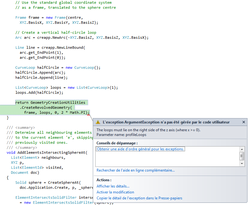
I fixed that by translating my loop definition to the same centre point as the frame, and end up with the following implementation:
  /// <summary>
  /// Create and return a solid sphere with
  /// a given radius and centre point.
  /// </summary>
  static public Solid CreateSphereAt(
    CreationApp creapp,
    XYZ centre,
    double radius )
  {
    // Use the standard global coordinate system
    // as a frame, translated to the sphere centre.

    Frame frame = new Frame( centre,
      XYZ.BasisX, XYZ.BasisY, XYZ.BasisZ );

    // Create a vertical half-circle loop;
    // this must be in the frame location.

    Arc arc = creapp.NewArc(
      centre - radius * XYZ.BasisZ,
      centre + radius * XYZ.BasisZ,
      centre + radius * XYZ.BasisX );

    Line line = creapp.NewLineBound(
      arc.get_EndPoint( 1 ),
      arc.get_EndPoint( 0 ) );

    CurveLoop halfCircle = new CurveLoop();
    halfCircle.Append( arc );
    halfCircle.Append( line );

    List<CurveLoop> loops = new List<CurveLoop>( 1 );
    loops.Add( halfCircle );

    return GeometryCreationUtilities
      .CreateRevolvedGeometry(
        frame, loops, 0, 2 * Math.PI );
  }
Displaying a Solid Using AVF
One of the uses of the transient solids created by the geometry creation utility class is for geometrical filtered element collection. Before we get to that, however, lets simply display a couple of spheres using the analysis visualisation framework AVF.
I copied and posted code from the samples mentioned above to create an AVF display style, get or create a SpatialFieldManager, and set up an analysis result schema. All this functionality is finally accessed by a simple call to the PaintSolid method.
Here is my external command Execute mainline implementation putting it all together:
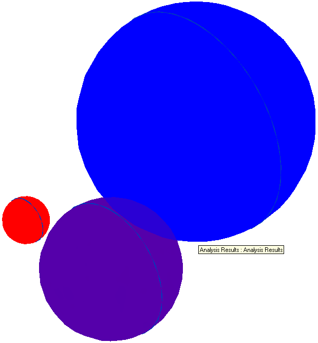
  public Result Execute(
    ExternalCommandData commandData,
    ref string message,
    ElementSet elements )
  {
    UIApplication uiapp = commandData.Application;
    UIDocument uidoc = uiapp.ActiveUIDocument;
    Application app = uiapp.Application;
    CreationApp creapp = app.Create;
    Document doc = uidoc.Document;

    Solid s1 = Command.CreateSphereAt(
      creapp, XYZ.Zero, 1.0 );

    Solid s2 = Command.CreateSphereAt(
      creapp, new XYZ( 44.051020645,
        80.747278319, 9.842519685 ), 1.0 );

    Solid s3 = Command.CreateSphereAt(
      creapp, 5 * XYZ.BasisX, 3.0 );

    Solid s4 = Command.CreateSphereAt(
      creapp, 10 * XYZ.BasisY, 5.0 );

    PaintSolid( doc, s1, 1.0 );
    PaintSolid( doc, s2, 2.0 );
    PaintSolid( doc, s3, 3.0 );
    PaintSolid( doc, s4, 4.0 );

    return Result.Succeeded;
  }
Some of the resulting spheres look like this in Revit:
Next things I am thinking of doing are using a sphere to define a localised geometrical filtered element collector, and also making use of Kean's Apollonian gasket and sphere packing web service to fill a sphere with solid spheres (project overview). The latter may not be all that useful in the BIM domain, but fun.