Set View Section Box to Match Scope Box
Here is a case that I really like, demonstrating two interesting aspects:
- How to retrieve the exact geometric location, size and orientation of the scope box.
- How to set the exact geometric location, size and orientation of the 3D view section box.
In fact, we show how to use the manually adjusted scope box to define the view section box, i.e. specifying exactly how the model is cut in the current 3D view.
I actually already showed how to set up a view section box discussing how to create a section view parallel to a wall.
The key is setting up the view SectionBox property properly. It takes a BoundingBoxXYZ input, i.e. a transform plus minimum and maximum values describing the location, orientation and size of the box. In that post, it is fed into the CreateSection method.
To manipulate an existing view instead of creating a new one, you simply set up the bounding box in the same way and assign it to the view SectionBox property as shown below.
Here is the discussion that led up to this solution:
Question: Here is a model in 3D view containing a scope box represented by the dotted lines. The 3D view SectionBox property is checked, so the view SectionBox is also shown, using solid lines. Both are selected, and thus highlighted in blue:
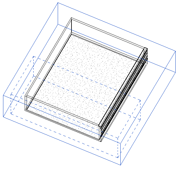
Our goal is to programmatically relocate and rotate the section box so it is at the same location and angle as the scope box, and also make the size of the section box the same as the scope box.
How can this be achieved, please?
Answer: You need to implement the following workflow, or rather data flow:
- Extract the required data from the scope box.
- Set up the required view SectionBox bounding box data, i.e. transform, min and max points.
- Apply the SectionBox data to the view.
The last step 3. is trivial: you simply say view.SectionBox = newSectionBox as shown below.
Step 2 is demonstrated by the discussion on how to create a section view parallel to a wall.
Step 1 requires reading and interpreting the scope box data. The scope box Location property data is not accessible, so you can't use that. As far as I can tell, the only thing you have to go by is its geometry definition.
Exploring the scope box geometry in RevitLookup, you can see that it consists of exactly twelve lines, the edges of the scope box parallelepiped itself.
You need to figure out the exact size and orientation from those twelve lines, and then decide how they should determine the view section box.
I implemented a sample command SetSectionBox to test the concept, and a method GetScopeBoxBoundingBox to extract the scope box line geometry data, create a bounding box from that, and assign it to the view section box.
It returns the minimal aligned bounding box for a Revit scope box element. The only information we can obtain from the scope box are its 12 boundary lines. Algorithm:
- Pick an arbitrary line as the X axis and its starting point as the origin.
- Find the three other lines starting or ending at the origin, and use them to define the Y and Z axes.
- If necessary, swap Y and Z to form a right-handed coordinate system.
Determining Coordinate System Right-Handedness
Ah, yes, before we get to that, how do we determine whether the three vectors form a right-handed coordinate system?
Well, the coordinate system is right handed if and only if the signed volume of the parallelepiped they span is positive. That volume is calculated by forming the cross product of the first two, then forming the dot product between the result and the third. This is also called Spatprodukt in German. Here are the two little one-line helper methods implementing this:
/// <summary>
/// Return the signed volume of the paralleliped
/// spanned by the vectors a, b and c. In German,
/// this is also known as Spatprodukt.
/// </summary>
static double SignedParallelipedVolume(
  XYZ a,
  XYZ b,
  XYZ c )
{
  return a.CrossProduct( b ).DotProduct( c );
}

/// <summary>
/// Return true if the three vectors a, b and c
/// form a right handed coordinate system, i.e.
/// the signed volume of the paralleliped spanned
/// by them is positive.
/// </summary>
bool IsRightHanded( XYZ a, XYZ b, XYZ c )
{
  return 0 < SignedParallelipedVolume( a, b, c );
}
Determining Bounding Box of Scope Box
With that out of the way, here is the code of GetScopeBoxBoundingBox implementing the functionality described above:
BoundingBoxXYZ GetScopeBoxBoundingBox(
  Element scopeBox )
{
  Document doc = scopeBox.Document;
  Application app = doc.Application;
  Options opt = app.Create.NewGeometryOptions();
  GeometryElement geo = scopeBox.get_Geometry( opt );
  int n = geo.Count<GeometryObject>();

  if( 12 != n )
  {
    throw new ArgumentException( "Expected exactly"
      + " 12 lines in scope box geometry" );
  }

  XYZ origin = null;
  XYZ vx = null;
  XYZ vy = null;
  XYZ vz = null;

  // Extract the X, Y and Z axes from the lines

  foreach( GeometryObject obj in geo )
  {
    Debug.Assert( obj is Line,
      "expected only lines in scope box geometry" );

    Line line = obj as Line;

    XYZ p = line.get_EndPoint( 0 );
    XYZ q = line.get_EndPoint( 1 );
    XYZ v = q - p;

    if( null == origin )
    {
      origin = p;
      vx = v;
    }
    else if( p.IsAlmostEqualTo( origin )
      || q.IsAlmostEqualTo( origin ) )
    {
      if( q.IsAlmostEqualTo( origin ) )
      {
        v = v.Negate();
      }
      if( null == vy )
      {
        Debug.Assert( IsPerpendicular( vx, v ),
          "expected orthogonal lines in scope box geometry" );

        vy = v;
      }
      else
      {
        Debug.Assert( null == vz,
          "expected exactly three orthogonal lines to originate in one point" );

        Debug.Assert( IsPerpendicular( vx, v ),
          "expected orthogonal lines in scope box geometry" );

        Debug.Assert( IsPerpendicular( vy, v ),
          "expected orthogonal lines in scope box geometry" );

        vz = v;

        if( !IsRightHanded( vx, vy, vz ) )
        {
          XYZ tmp = vz;
          vz = vy;
          vy = tmp;
        }
        break;
      }
    }
  }

  // Set up the transform

  Transform t = Transform.Identity;
  t.Origin = origin;
  t.BasisX = vx.Normalize();
  t.BasisY = vy.Normalize();
  t.BasisZ = vz.Normalize();

  Debug.Assert( t.IsConformal,
    "expected resulting transform to be conformal" );

  // Set up the bounding box

  BoundingBoxXYZ bb = new BoundingBoxXYZ();
  bb.Transform = t;
  bb.Min = XYZ.Zero;
  bb.Max = vx + vy + vz;

  return bb;
}
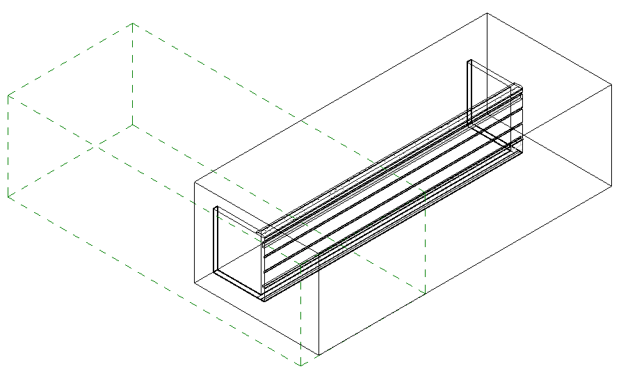
The result is close, but no cigar yet:
Determining Suitable View Section Box from Scope Box
In a next step, I decided to ensure that the Z axis I define actually is vertical and pointing upwards, take the view direction into account as well, and use the scope box edge closest to the viewer as the section box Z axis.
I therefore implemented a new method GetSectionBoundingBoxFromScopeBox, which returns a suitable bounding box for a Revit section view from the scope box position, taking the view direction into account, by performing the following steps:
- Find vertical edge closest to viewer.
- Use its bottom endpoint as the origin.
- Find the other two edges emanating from the origin.
- Use the three edges for the bounding box definition.
To find the vertical edge closest to the viewer, the view direction and scope box bounding box giving its maximum size are used together to determine a view point from which we imagine we are looking at the scope box.
I loop through the twelve lines in the scope box geometry twice. In the first loop, I determine the origin and Z axis. In the second, the X and Y axes are determined as well, based on that information.
The implementation looks like this:
BoundingBoxXYZ GetSectionBoundingBoxFromScopeBox(
  Element scopeBox,
  XYZ viewdirTowardViewer )
{
  Document doc = scopeBox.Document;
  Application app = doc.Application;

  // Determine a possible view point outside the
  // scope box extents in the direction of the
  // viewer.

  BoundingBoxXYZ bb
    = scopeBox.get_BoundingBox( null );

  XYZ v = bb.Max - bb.Min;

  double size = v.GetLength();

  XYZ viewPoint = bb.Min
    + 10 * size * viewdirTowardViewer;

  // Retrieve scope box geometry,
  // consisting of exactly twelve lines.

  Options opt = app.Create.NewGeometryOptions();
  GeometryElement geo = scopeBox.get_Geometry( opt );
  int n = geo.Count<GeometryObject>();

  if( 12 != n )
  {
    throw new ArgumentException( "Expected exactly"
      + " 12 lines in scope box geometry" );
  }

  // Determine origin as the bottom endpoint of
  // the edge closest to the viewer, and vz as the
  // vertical upwards pointing vector emanating
  // from it. (Todo: if several edges are equally
  // close, pick the leftmost one, assuming the
  // given view direction and Z is upwards.)

  double dist = double.MaxValue;
  XYZ origin = null;
  XYZ vx = null;
  XYZ vy = null;
  XYZ vz = null;
  XYZ p, q;

  foreach( GeometryObject obj in geo )
  {
    Debug.Assert( obj is Line,
      "expected only lines in scope box geometry" );

    Line line = obj as Line;

    p = line.get_EndPoint( 0 );
    q = line.get_EndPoint( 1 );
    v = q - p;

    if( IsVertical( v ) )
    {
      if( q.Z < p.Z )
      {
        p = q;
        v = v.Negate();
      }

      if( p.DistanceTo( viewPoint ) < dist )
      {
        origin = p;
        dist = origin.DistanceTo( viewPoint );
        vz = v;
      }
    }
  }

  // Find the other two axes emanating from the
  // origin, vx and vy, and ensure right-handedness

  foreach( GeometryObject obj in geo )
  {
    Line line = obj as Line;

    p = line.get_EndPoint( 0 );
    q = line.get_EndPoint( 1 );
    v = q - p;

    if( IsVertical( v ) ) // already handled this
    {
      continue;
    }

    if( p.IsAlmostEqualTo( origin )
      || q.IsAlmostEqualTo( origin ) )
    {
      if( q.IsAlmostEqualTo( origin ) )
      {
        v = v.Negate();
      }
      if( null == vx )
      {
        Debug.Assert( IsPerpendicular( vz, v ),
          "expected orthogonal lines in scope box geometry" );

        vx = v;
      }
      else
      {
        Debug.Assert( null == vy,
          "expected exactly three orthogonal lines to originate in one point" );

        Debug.Assert( IsPerpendicular( vz, v ),
          "expected orthogonal lines in scope box geometry" );

        Debug.Assert( IsPerpendicular( vx, v ),
          "expected orthogonal lines in scope box geometry" );

        vy = v;

        if( !IsRightHanded( vx, vy, vz ) )
        {
          XYZ tmp = vx;
          vx = vy;
          vy = tmp;
        }
        break;
      }
    }
  }

  // Set up the transform

  Transform t = Transform.Identity;
  t.Origin = origin;
  t.BasisX = vx.Normalize();
  t.BasisY = vy.Normalize();
  t.BasisZ = vz.Normalize();

  Debug.Assert( t.IsConformal,
    "expected resulting transform to be conformal" );

  // Set up the bounding box

  bb = new BoundingBoxXYZ();
  bb.Transform = t;
  bb.Min = XYZ.Zero;
  bb.Max = vx + vy + vz;

  return bb;
}
Putting it Together
Finally, let's take a look at the Execute method tying together and making use of this functionality.
For quick testing purposes, it assumes that a 3D view is currently active, and picks the first (only) scope box element it encounters. It performs the following steps:
- Access the current view and test that it is a 3D one.
- Select the scope box element.
- Determine the new view section box from the scope box using the GetSectionBoundingBoxFromScopeBox method, taking the view direction into account.
- Assign the new view section box definition to the view SectionBox property.
Here is the code:
  UIApplication uiapp = commandData.Application;
  UIDocument uidoc = uiapp.ActiveUIDocument;
  Application app = uiapp.Application;
  Document doc = uidoc.Document;

  View3D view = doc.ActiveView as View3D;

  if( null == view )
  {
    message = "Please run this command in a 3D view.";
    return Result.Failed;
  }

  Element scopeBox
    = new FilteredElementCollector( doc, view.Id )
      .OfCategory( BuiltInCategory.OST_VolumeOfInterest )
      .WhereElementIsNotElementType()
      .FirstElement();

  BoundingBoxXYZ viewSectionBox
    = GetSectionBoundingBoxFromScopeBox(
      scopeBox, view.ViewDirection );

  using( Transaction tx = new Transaction( doc ) )
  {
    tx.Start( "Move And Resize Section Box" );

    view.SectionBox = viewSectionBox;

    tx.Commit();
  }
  return Result.Succeeded;
The result in the original model looks like this, which is exactly what we were after:
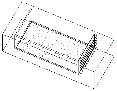
The dotted lines representing the scope box are completely obscured by the continuous view section box lines after running the command.
Nice, huh?
Here is SetSectionBox.zip containing the complete source code, Visual Studio solution, and add-in manifest of this command.