Graphically Display Area Boundary Loops
I recently worked on a case from a developer struggling with area boundary loops and attempting to determine whether they were closed or not by looking at the coordinate values in RevitLookup.
I hold that the average human brain is overtaxed by trying to analyse graphics manually, or rather, cerebrally.
I therefore implemented a sample command DisplayBoundary to display them graphically instead.
It iterates over the boundary segments of selected areas, or all areas in the model, and creates a model curve to represent each segment.
After running the command, the model curves can be isolated to display the result graphically.
Area Boundary Segment Retrieval Options
The Area.GetBoundarySegments method takes a SpatialElementBoundaryOptions argument, which enables us to specify the two properties StoreFreeBoundaryFaces and SpatialElementBoundaryLocation.
The former indicates whether to include free boundary faces in the result, i.e. portions of spatial element faces that are not coincident with bounding element faces.
The latter can be set to either Finish, to retrieve the spatial element finish face, or Center, for its centerline.
Since the Revit wall location definition relies heavily on centerlines, the latter setting is preferable in order to obtain closed loops from the boundary segment results.
Example
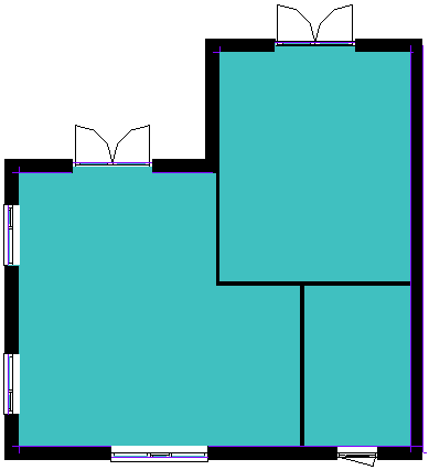
Here is a simple sample area to test this on:
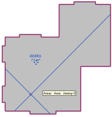
Its serrated edges stem from various openings in the walls of the underlying rooms:
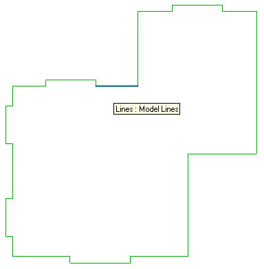
Selecting this area element and running the DisplayBoundary command generates a model curve for each boundary segment. Isolating model lines in the view shows the area outline:
Code
The code to achieve this is astonishingly simple and succinct, although it has not been tested extensively yet:
public Result Execute(
  ExternalCommandData commandData,
  ref string message,
  ElementSet elements )
{
  UIApplication uiapp = commandData.Application;
  UIDocument uidoc = uiapp.ActiveUIDocument;
  Application app = uiapp.Application;
  Document doc = uidoc.Document;

  FilteredElementCollector col = null;

  // Access current selection

  ElementSet set = uidoc.Selection.Elements;

  int n = set.Size;

  if( 0 < n )
  {
    List<ElementId> ids
      = new List<ElementId>( set
        .OfType<Area>()
        .Select<Area,ElementId>( e => e.Id ) );


    if( 0 == ids.Count )
    {
      message = "Please select some area alements "
        + " before running his command, or nothing "
        + "at all to process all of them.";

      return Result.Failed;
    }

    // When instantiating a filtered element
    // collector using preselected elements,
    // you still must apply a filter, even if
    // it has no effect, or the collector will
    // throw an exception when accessing its
    // elements:

    col = new FilteredElementCollector( doc, ids )
      .WhereElementIsNotElementType();
  }
  else
  {
    // Retrieve all area elements from database

    col = new FilteredElementCollector( doc )
      .OfClass( typeof( Area ) );
  }

  // Specify boundary options

  SpatialElementBoundaryOptions opt
    = new SpatialElementBoundaryOptions();

  opt.StoreFreeBoundaryFaces = true;

  opt.SpatialElementBoundaryLocation =
    SpatialElementBoundaryLocation.Center; // loops closed
    //SpatialElementBoundaryLocation.Finish; // loops not closed

  using( Transaction tx = new Transaction( doc ) )
  {
    tx.Start( "Convert Area Loops To Model Curves" );

    // Filtered element collector is iterable

    foreach( Area area in col )
    {
      Debug.Print( area.Name );

      double z = area.Level.Elevation;

      Plane levelPlane = app.Create.NewPlane(
        XYZ.BasisZ, new XYZ( 0, 0, z ) );

      SketchPlane sketchPlane
        = doc.Create.NewSketchPlane( levelPlane );

      sketchPlane.Name = "Model Curves for Area "
        + area.Id.ToString();

      IList<IList<BoundarySegment>> loops
        = area.GetBoundarySegments( opt );

      foreach( IList<BoundarySegment> loop in loops )
      {
        foreach( BoundarySegment seg in loop )
        {
          doc.Create.NewModelCurve(
            seg.Curve, sketchPlane );
        }
      }
    }

    tx.Commit();
  }
  return Result.Succeeded;
}
Here is DisplayBoundary.zip including the complete source code, Visual Studio solution, and add-in manifest for this command.
Unicode Characters in IFC
On a completely different topic, here is a recent question that came up:
Question: How are Chinese characters exported to an IFC file?
I see an entry like this in my output file:
  #53 = IFCPROJECT(
    '2ZorIEY491exwHFgtoAWmP',#52,
    '\X2\987976EE7F1653F7\X0\',$,$,
    '\X2\987976EE540D79F0\X0\',
    '\X2\987976EE72B66001\X0\',
    (#42,#47),#35);
I do not recognise this format.
Can you explain, please?
Answer: All strings in IFC files are in Unicode. They are encoded according to the rules described in the buildingSMART string encoding and decoding summary.
Create Assemblies Sample
My colleague Katsuaki Takamizawa just published a Revit 2013 port and demonstration of the assembly creation and comparison source code sample provided by the Revit 2012 API webcast recording.
It implements two external commands:
- CreateAssemblies lets you pick elements and creates an assembly instance and a part list in a schedule view.
- Compare Assemblies asks you to select two assembly instances and finds differences such as the number or types of elements.