Structural Concrete Setout Point Add-in
I am back from my vacation now, having spent a wonderful relaxing time doing all kinds of things not related to the Revit API or computers at all, such as talking, walking, singing, playing music, painting, swimming, meditating, climbing, caving, canoeing and sharing time with friends...
Meanwhile, a whole bunch of interesting issues to share with you have been piling up, new ones keep pouring in, and I still have some long-standing pending posts to get around to as well.
One important utility that I have been wanting to publish for months now is for the automatic placement and management of structural concrete setout points which I implemented together with Paul Hellawell of GHD at the Melbourne DevLab back in March, thus also finally answering Ishfak's request for the full Revit 2013 source code to retrieve real world concrete coordinates.
It is a full-blown end-user-capable little application for the automatic creation of setout points for on-site location and construction of structural elements.
One of the most fascinating aspects of the implementation for me was the amount of choices that we were forced to make between implementing something ourselves programmatically versus discovering the proper way to use built-in Revit functionality to do it automatically for us instead with no work at all on our part.
For instance, we originally defined one single setout point marker type, and started implementing API functionality to select the main points and change their colour.
Happily, we soon found a much simpler solution which requires no programming at all: simply define two separate family types for the minor and major setout point markers with different colours, and let the user select which one to use through the standard Revit user interface. Several other equally important design decisions cropped up, demonstrating the importance of knowing the product well, which Paul luckily does.
They really highlighted the fact how important it is to know the user interface and best standard practices in depth before embarking on a serious programming project, however simple it may seem.
Let's start at the beginning, and reiterate the motivation for this undertaking:
Almost every construction professional has experienced the following kind of situation at some time in their career:
A large complex structure is constructed off-site. When assembled on site, it does not fit exactly. The workers continue nonetheless and force it into place. The error is discovered later and corrected using brute force and post adaption. Overall cost of exercise: days or weeks of delay and painful cost overruns.
This leads to the following important prophylactic task:
The Challenge: Provide a way to find the real world coordinates of the corners of potential elements to be set out in the field, automatically extracting relevant setout points from the model. In this example, we are dealing with concrete structural elements. Ideally, we would like to display these points in a Revit schedule, so that they can be formatted and placed on a drawing sheet. We would like to then define which of the points should be used as main setout points and list them in a schedule, preferably numbered sequentially for readability.
In Practice: Retrieved all the concrete corner point data via the API is not hard, and I presented the solution to retrieve real world concrete coordinates separately in the following three steps:
- Filtering for structural concrete elements.
- Retrieving their corners, i.e. geometry traversal to retrieve unique vertices.
- Converting from Revit model to real-world coordinates.
However, transferring this information directly into a schedule proved to be impossible. Instead we created a family definition containing shared parameters to hold the data required for scheduling. We then place instances of the family at the points extracted from the geometry. Through the API it is now possible to populate the parameters with the X, Y, Z coordinates extracted from the geometry, and add these values to the extracted project location, to convert them to real world coordinates.
Initially, we defined a setout point family with one single type in it. This did not enable the ability to select which points to schedule as main setout points. For this, we created two different family types, SetoutPoint_Major and SetoutPoint_Minor. This allows two separate schedules to be created, one capturing all the points, the other only points defined as major points for use on a drawing sheet for setout.
The schedule listing all points is useful, e.g. for export to a CSV file and subsequent import into a surveying device such as a Trimble, allowing site set-out directly from the model.
The setout point tool extracts the X, Y, Z coordinates of all concrete edges. The generated points can then be interactively marked as Major points (setout point) and renumbered sequentially to provide a schedule of key setout points. The remaining point are schedules as well, e.g. to be saved as a comma delimitated file CSV file to be sent to surveying equipment for site setout.
Usage
Ensure your project contains some elements whose structural material is set to concrete or precast concrete.
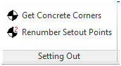
You can then click the Get Concrete Corners tool:
The tool automatically analyses al the concrete structural elements' geometry and placed setout point family instances representing a 3D pointer on all the concrete element corner vertices:
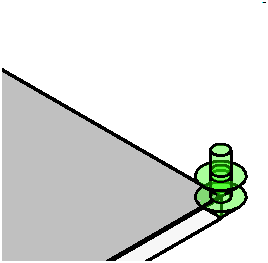
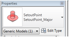
The family is defined using the Generic Model family template. The green indicators represent general setout points. You can select the ones you want to change to main setout points, also known as major or key, by simply selecting them and swapping their type to SetoutPoint_Major:
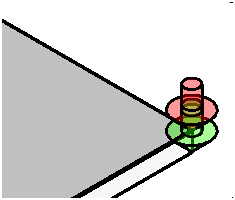
Major setout points are displayed in red instead of green:
The sample project provided defines two schedules. One of them is populated with all setout points, marking every corner of every piece of concrete:
The second schedule lists only the selected main or major setout points and their coordinates:
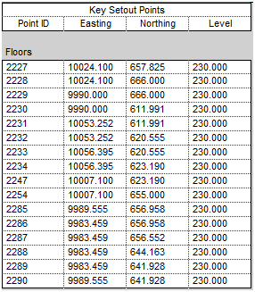
Once you have all your key setout points defined, a separate 'Renumber setout Points' external command renumbers them sequentially and adds a SOP (Set Out Point) prefix to their number to differentiate them from the minor points.
The renumbered schedule can now be used on a drawing sheet.
Many thanks to Paul for our initiating this project, his deep Revit knowledge and experience, all the support he provided during the Melbourne Revit API training, and the great evening we had together in Melbourne after the training!
Implementation Details
I already pointed to the discussion of the main technical underpinnings for the retrieval of the concrete corners above, i.e.
- Filtering for structural concrete elements.
- Retrieving their corners, i.e. geometry traversal to retrieve unique vertices.
- Converting from Revit model to real-world coordinates.
Now let's look at some of the aspects of putting this functionality to use and wrapping it into a full-blown end-user application:
- External application and CmdData class
- Shared parameters
- Importance of product usage experience, content and best practices
- Marking all geometry vertices
- Major setout point renumbering
External Application and CmdData Class
The application defines two commands:
- CmdGeomVertices: filter for all relevant concrete structural elements, analyse their geometry, create the setout point markers, and populate their shared parameters to be reflected in the predefined schedules.
- CmdRenumber: renumber the main or major setout points consecutively.
They are presented in a custom ribbon panel defined by an external application.
In order to encapsulate all the information required to populate the ribbon panel push buttons, I define the following CmdData class defining the external command implementation class name, description and tool tip text:
  class CmdData
  {
    public CmdData(
      string name,
      string text,
      string tip )
    {
      Name = name;
      Text = text;
      Tip = tip;
    }
    public string Name { get; set; }
    public string Text { get; set; }
    public string Tip { get; set; }
  }
The two instances can be populated like this:
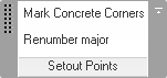
  static CmdData[] data = new CmdData[] {

    new CmdData(
      "GeomVertices",
      "Mark Concrete Corners",
      "Place a setout point marker on every concrete corner." ),

    new CmdData(
      "Renumber",
      "Renumber major",
      "Renumber major setout points" )
  };
The external application OnStartup method making use of this ends up very simple:
  public Result OnStartup(
    UIControlledApplication a )
  {
    string path = System.Reflection.Assembly
      .GetExecutingAssembly().Location;

    // Create ribbon panel

    RibbonPanel p = a.CreateRibbonPanel( Caption );

    // Create buttons

    List<PushButtonData> buttonData
      = new List<PushButtonData>(
        data.Length );

    foreach( CmdData cd in data )
    {
      PushButtonData pbd = new PushButtonData(
        cd.Name, cd.Text, path,
        _class_name_prefix + cd.Name );

      pbd.ToolTip = cd.Tip;

      buttonData.Add( pbd );
    }

    p.AddStackedItems( buttonData[0],
      buttonData[1] );

    return Result.Succeeded;
  }
Lacking icons, my panel does not look quite as impressive as Paul's one shown above, but it does the job:
Shared Parameters
As mentioned above, the functionality to retrieve the concrete corners geometry data has already been described in previous posts.
The question is how to handle this information in order to make it available to the user, populate schedules, etc. We ended up inserting family instances marking all concrete corners as minor setout points, and populating shared parameters on each to encapsulate the required data specifying the host element and its point coordinates. Here is the shared parameter file, slightly simplified for readability:
# This is a Revit shared parameter file.
# Do not edit manually.
*META VERSION MINVERSION
META 2 1
*GROUP ID NAME
GROUP  1 SetOut
*PARAM GUID NAME             DATATYPE ... GROUP VISIBLE
PARAM  .... Key_Setout_Point YESNO        1     1
PARAM  .... Host_Type        TEXT         1     1
PARAM  .... Host_Id          INTEGER      1     1
PARAM  .... X                LENGTH       1     1
PARAM  .... Y                LENGTH       1     1
PARAM  .... Z                LENGTH       1     1
PARAM  .... Point_Number     TEXT         1     1
Shared parameter access is implemented using their GUIDs throughout the code.
Importance of Product Usage Experience, Content and Best Practices
We initially defined a parameter in the setout point family to distinguish between minor and major points, and started working on a separate user interface to toggle between the two and change the family instance colour depending on its current setting.
At a certain point, we discovered that it was vastly simpler to define two separate types within the family instead and use the standard Revit user interface to toggle between those.
It is so important for every add-in developer to know the standard Revit possibilities and best-practice workflows.
That can save huge amounts of unnecessary programming effort, sometimes wasted to fight against the product and its standard paradigms instead of making optimal use of it.
Marking All Geometry Vertices
As said, most of the underlying functionality to retrieve the concrete corner geometry was already presented and discussed.
One additional helper method GetFamilySymbols loads the setout point family, if it is not already present, and retrieves the major and minor setout point symbols:
public static FamilySymbol [] GetFamilySymbols(
  Document doc,
  bool loadIt )
{
  FamilySymbol [] symbols = null;

  Family family
    = new FilteredElementCollector( doc )
      .OfClass( typeof( Family ) )
      .FirstOrDefault<Element>(
        e => e.Name.Equals( FamilyName ) )
      as Family;

  // If the family is not already loaded, do so:

  if( null == family && loadIt )
  {
    // Load the setout point family

    using( Transaction tx = new Transaction(
      doc ) )
    {
      tx.Start( "Load Setout Point Family" );

      if( doc.LoadFamily( _family_path,
        out family ) )
      {
        tx.Commit();
      }
      else
      {
        tx.RollBack();
      }
    }
  }

  if( null != family )
  {
    symbols = new FamilySymbol[2];

    int i = 0;

    foreach( FamilySymbol s in family.Symbols )
    {
      symbols[i++] = s;
    }

    Debug.Assert(
      symbols[0].Name.EndsWith( "Major" ),
      "expected major (key) setout point first" );

    Debug.Assert(
      symbols[1].Name.EndsWith( "Minor" ),
      "expected minor setout point second" );
  }
  return symbols;
}
Then, finally, here is the external command mainline pulling it all together, i.e.
- Determine project location transformation to real world coordinates.
- Load or retrieve setout point family symbols.
- Retrieve the relevant structural concrete elements.
- Retrieve element geometry.
- Place a setout point marker family instance on each geometry vertex.
- Check to see whether the required shared parameters have been bound.
Setout points are numbered starting at one each time the command is run with no decoration or prefix.
Here is Execute method implementation performing these tasks:
  UIApplication uiapp = commandData.Application;
  UIDocument uidoc = uiapp.ActiveUIDocument;
  Application app = uiapp.Application;
  Document doc = uidoc.Document;

  Transform projectLocationTransform
    = GetProjectLocationTransform( doc );

  // Load or retrieve setout point family symbols:

  FamilySymbol [] symbols
    = GetFamilySymbols( doc, true );

  if( null == symbols )
  {
    message = string.Format(
      "Unable to load setout point family from '{1}'.",
      _family_path );

    return Result.Failed;
  }

  FilteredElementCollector col
    = GetStructuralElements( doc );

  // Retrieve element geometry and place a
  // setout point on each geometry corner.

  // Setout points are numbered starting at
  // one each time the command is run with
  // no decoration or prefix whatsoever.

  using( Transaction tx = new Transaction( doc ) )
  {
    tx.Start( "Place Setout Points" );

    Options opt = app.Create.NewGeometryOptions();

    // On the very first attempt only, run an error
    // check to see whether the required shared
    // parameters have actually been bound:

    bool first = true;

    foreach( Element e in col )
    {
      Solid solid = GetSolid( e, opt );

      string desc = ElementDescription( e );

      if( null == solid )
      {
        Debug.Print(
          "Unable to access element solid for element {0}.",
          desc );

        continue;
      }

      Dictionary<XYZ, int> corners
        = GetCorners( solid );

      int n = corners.Count;

      Debug.Print( "{0}: {1} corners found:", desc, n );

      foreach( XYZ p in corners.Keys )
      {
        ++_point_number;

        Debug.Print( "  {0}: {1}",
          _point_number, PointString( p ) );

        FamilyInstance fi
          = doc.Create.NewFamilyInstance( p,
            symbols[1], StructuralType.NonStructural );

        // Add shared parameter data immediately
        // after creating the new family instance.
        // The shared parameters are indeed added
        // immediately by Revit, so we can access and
        // populate them.
        // No need to commit the transaction that
        // added the family instance to give Revit
        // a chance to add the shared parameters to
        // it, nor to regenerate the document, we
        // can write the shared parameter values
        // right away.

        if( first )
        {
          Parameter q = fi.get_Parameter(
            _parameter_x );

          if( null == q )
          {
            message =
              "The required shared parameters "
              + "X, Y, Z, Host_Id, Host_Type and "
              + "Point_Number are missing.";

            tx.RollBack();

            return Result.Failed;
          }
          first = false;
        }

        // Transform insertion point by applying
        // project location transformation.

        XYZ r2 = projectLocationTransform.OfPoint( p );

        fi.get_Parameter( _parameter_host_type ).Set(
          GetHostType( e ).ToString() );

        fi.get_Parameter( _parameter_host_id ).Set(
          e.Id.IntegerValue );

        fi.get_Parameter( _parameter_point_nr ).Set(
          _point_number.ToString() );

        fi.get_Parameter( _parameter_x ).Set( r2.X );
        fi.get_Parameter( _parameter_y ).Set( r2.Y );
        fi.get_Parameter( _parameter_z ).Set( r2.Z );
      }
    }

    tx.Commit();
  }
  return Result.Succeeded;
That's about it... one more little thing:
Major Setout Point Renumbering
Such irrational creatures, these human beings.
Users apparently insist on consecutive numbering of items they deal with.
We therefore implemented a second command named CmdRenumber to renumber the major points.
They are basically renumbered randomly, since all major points are selected using a filtered element collector. We iterate over the result, assign a consecutive number to each instance, and store it in the Point_Number text-valued shared parameter with a "SOP " prefix string _sop_prefix.
The key setout points are family instances with the generic model category and the major setout point type.
The external command Execute implementation thus ends up looking like this:
  UIApplication uiapp = commandData.Application;
  UIDocument uidoc = uiapp.ActiveUIDocument;
  Document doc = uidoc.Document;

  FamilySymbol[] symbols
    = CmdGeomVertices.GetFamilySymbols(
      doc, false );

  if( null == symbols )
  {
    TaskDialog.Show( "Setout Points",
      "Setout point family not loaded, "
      + "so no setout points present." );

    return Result.Succeeded;
  }

  FamilyInstanceFilter instanceFilter
    = new FamilyInstanceFilter( doc, symbols[0].Id );

  FilteredElementCollector col
    = new FilteredElementCollector( doc )
      .OfCategory( BuiltInCategory.OST_GenericModel )
      .OfClass( typeof( FamilyInstance ) )
      .WherePasses( instanceFilter );

  Guid guid = CmdGeomVertices._parameter_point_nr;

  using( Transaction tx = new Transaction( doc ) )
  {
    tx.Start( "Renumber Setout Points" );

    int i = 0;
    string s;

    foreach( Element p in col )
    {
      s = _sop_prefix + ( ++i ).ToString();

      p.get_Parameter( guid ).Set( s );
    }

    tx.Commit();
  }
  return Result.Succeeded;
For all further details, please refer to the one and only really trustworthy reference, the full source code.
Here is SetoutPoints.zip including the complete source code, Visual Studio solution, add-in manifest and setout point marker family.
For easier testing, here is also a sample project based on the standard rst_basic_sample_project.rvt with a non-standard project location and the setout point schedules added.
Addendum: I migrated this to Revit 2015 and created the SetoutPoints GitHub repository for it.