Connector Orientation
Today is the Pentecost or Whit Monday holiday in Neuchâtel, and I am in full tilt preparing for the AEC DevCamp in Waltham next week.
I will be presenting sessions on the new Revit 2013 UI API features, the Revit MEP API, and extensible storage.
I am of course looking forward much more to the many exciting other presentations by my colleagues in the ADN DevTech AEC team and especially by members of the Revit development team, directly from the horse's mouth, so to speak. Have a look at the session list and descriptions to see them all in their full glory.
Meanwhile, here is yet another MEP related topic to pick up:
Two years ago, I presented a solution for determining the width and height orientation of a Revit MEP connector.
Now Martin Schmid describes a new useful aspect of this issue which also leads to a very important point on real numbers comparisons.
Question: How do I determine the orientation of a connector in my project? From Revit Lookup, I can find where the information is, but I'm not sure how to interpret this without a 'visual'.
Answer: It was easy enough to determine by exporting a simple Revit model to AutoCAD, and displaying the coordinate entries there.
I thought I would share what I found to save other users from having to go through the same research.
For a FamilyInstance, such as a pipe fitting, the information can be found via
- FamilyInstance > MEPModel > ConnectorManager > ConnectorSet > Connector > CoordinateSystem
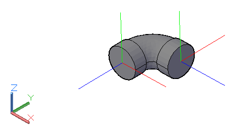
As the image below shows, the Z coordinate of CoordinateSystem indicates the normal direction of the connector. The CoordinateSystem.Origin is the actual location in the model:
For a MEPCurve such as a pipe, the access is slightly different:
- MEPCurve > ConnectorManager > ConnectorSet > Connector > CoordinateSystem
So, if you're trying to determine if two connectors are parallel and facing opposite directions, you can test that the Z axis vectors of the two connectors' CoordinateSystem properties pointing in exactly opposite directions, i.e. one equals the negation of the other.
Many thanks to Martin for this explanation!
Real Number Equality Testing
Jeremy adds: since the connector CoordinateSystem Z axis vector is an XYZ instance, i.e. a triple of three real numbers, comparing their equality leads back to a floating point number comparison.
In this case, you should actually almost never ever use an exact equality comparison such as Equals, or '=='.
You need to use an appropriate real number equality test instead.
Our guru GNU says: "we recommend that you consider not comparing real numbers for exact equality with the == operator, but rather check that real numbers are within an acceptable tolerance".
For the Revit API XYZ point and vector instances, this can easily be achieved by using the IsAlmostEqualTo method instead.
The comparison between the two connectors' CoordinateSystem Z axis vectors can therefore be implemented like this, for example:
  conn1.CoordinateSystem.BasisZ.IsAlmostEqualTo(
    -conn2.CoordinateSystem.BasisZ );
I already discussed taking this one step further several times, for instance to implement the XyzEqualityComparer for retrieving unique geometry vertices, nested instance geometry, toposurface point classification and accessing the top faces of a sloped wall.