Hosting a Light Fitting on a Reference Plane
It is sometimes a challenge to determine which of the numerous overloads of the NewFamilyInstance method to use to achieve a desired effect. Here is a question on using it to host a light fitting by Simon Jones, with an initial answer by Saikat Bhattacharya, followed by lots more research by Simon to nail down the right solution that really works.
Question: How can I host a light fitting onto a reference plane?
I tried several different ways without any luck so far.
When I use the following, the light is hosted by the reference plane but doesn't move with it:
  mRevitDoc.Document.Create.NewFamilyInstance(
    pt, mFamilySymbol, refDir, mReferencePlane,
    StructuralType.NonStructural);
What should I use instead to make the fitting remain attached to the plane at all times?
Answer: The following modification to your code addresses your requirement.
It uses the overload of NewFamilyInstance taking a reference, point, vector and symbol to insert a new instance of a family onto a face referenced by the input Reference instance, using a location and reference direction.
This creates a family instance which moves when the ReferencePlane is moved.
For simplicity, I have hard coded the element id of the ReferencePlane of my test project.
Before running this code, please select the lighting instance on the base work plane. This code then creates a lighting instance on the reference plane (along with the existing lighting fixture on the reference).
Now you can move the reference plane to the other side of the wall and confirm that the new lighting fixture instance moves along with it too.
  Selection sel = uidoc.Selection;

  ElementSet elemSet = sel.Elements;

  Transaction trans = new Transaction( doc );
  trans.Start( "Lights Camera Action!" );

  IEnumerator iter = elemSet.ForwardIterator();

  Element element;

  ReferencePlane mReferencePlane = null;
  FamilyInstance mFamilyInstance = null;
  FamilySymbol mFamilySymbol = null;

  while( iter.MoveNext() )
  {
    element = iter.Current as Element;

    FamilyInstance fi = element as FamilyInstance;

    mFamilyInstance = fi;
    mFamilySymbol = fi.Symbol;
  }

  mReferencePlane = doc.get_Element(
    new ElementId( 615738 ) ) as ReferencePlane;

  XYZ pt = XYZ.Zero;
  XYZ refDir = XYZ.BasisZ;

  uidoc.Document.Create.NewFamilyInstance(
    mReferencePlane.Reference, pt, refDir,
    mFamilySymbol );

  trans.Commit();
Response: Perfect, got it working now.
The issue was that I was trying to place the light on a horizontal reference plane and it seems that the Before that, I was using:
That caused my error.
Here is a current snapshot of my
C# code and some
sample input data.
The code will read a TXT file and place lights on a named reference plane.
I explored the effect of the reference direction used in more detail.
Here are my findings:
The reference direction required obviously depends on the orientation of the reference plane.
So I guess the sensible thing to do is to use a direction relative to the plane's normal.
However, my solution requires taking ceiling layouts from AutoCAD and reading them into Revit via a txt file exported from AutoCAD.
Within Revit we use horizontal reference planes drawn from right to left (as even with manual insertion that effects the orientation of the light); therefore, this is the solution I require and am happy that I have.
From what I can work out, the reference direction needs to point in the direction the reference plane is drawn; therefore 0,0,1 works for vertical planes, and 1,0,0 for horizontal ones.
For a quick hack, the following works for both vertical and horizontal ref planes:
Here are the results of my tests prior to adding the above hack:
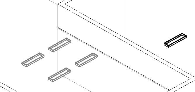
1. Vertical RP +ve Y (drawn bottom to top), RefDir 0,0,1: 2. Vertical RP -ve Y (drawn top to bottom), RefDir 0,0,1: Result: The lights have been placed on the other side of the reference plane.
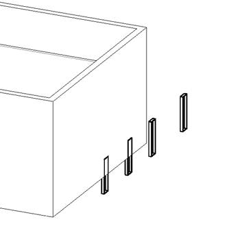
3. Vertical RP -ve Y (drawn top to bottom), RefDir 0,0,0: Result: Same side of ref plane, but now they're rotated around 90 degrees.
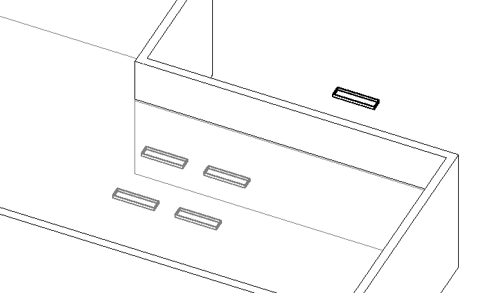
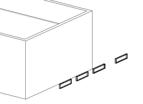
4. Horizontal RP -ve X (drawn right to left), RefDir 0,0,0: Result: Attached to the underside of the reference plane (as required).
5. Horizontal RP +ve X (drawn left to right), RefDir 0,0,0: Result: Attached to the topside of the reference plane (not as required).
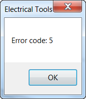
6. Horizontal RP +ve X (drawn left to right), RefDir 0,0,1 & Horizontal RP -ve X (drawn right to left), RefDir 0,0,1:
Result: 'Error code: 5'.
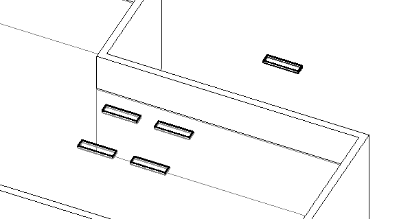
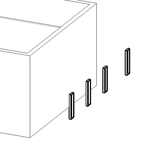
7. Horizontal RP -ve X (drawn right to left), RefDir 1,0,0:
Result: Look OK.
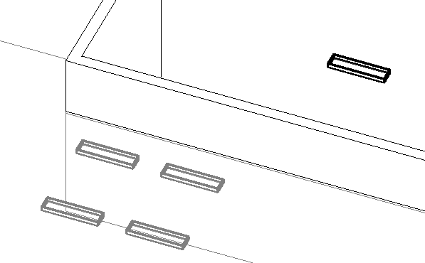
8. Horizontal RP -ve X (drawn right to left), RefDir 0,1,0:
Result: Lights rotated 90 degrees.
Many thanks to Simon and Saikat for this example and all the research!
XYZ refDir = new XYZ(0,0,0);
XYZ refDir = new XYZ(0,0,1);
  XYZ refDir = new XYZ(
    rp.Normal.Z, rp.Normal.X, rp.Normal.Y );
Vertical Reference Plane along the End Wall
Horizontal Reference Plane along the Underside of the Ceiling