Section View Geometry Not Cropped
Here is a nice little chat with some interesting resulting hints that I had with an Australian programmer Bo that clarify the retrieval of geometry from a section view. The main point is that the cutting plane of the section view does affect the retrieved geometry, whereas the view's bounding box does not. Here is the path we took to clarify this in all its gory detail:
Question: I am working on a structural concrete design application and would like to export Revit projects to it for analysis. I read your recent discussion of the curved analytical model approximation and ETABS structural link, which gives me a very good direction, since I intend to do something very similar.
However, the definition of floors in my application is such that the floor data exported cannot be just a list of lines. It has to be cut by section planes into series of 2D cross section shapes. Here is an example of a floor (white colour) and series of red section planes cutting it:
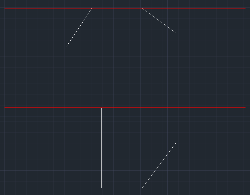
The cross section on each red plane would normally be rectangular. It might also be a very complex polygon with void holes in it, however.
The question is: how do I programmatically retrieve those cross section shapes?
Answer: You can easily extract the cross section shapes from the floor geometry by defining appropriate section views in Revit and asking the floor for its geometry in that specific view, as described by Saeed Karshenas in the note on section view geometry.
Response: I followed your suggestion and made some progress. I also have a couple of more questions:
Question 1: I drew a very rough floor with some beans and columns. I want to create a section view that is in the mid of the floor, half of the floor width (X), 1/10 of the floor height (Y) and the whole floor thickness (Z), like this:
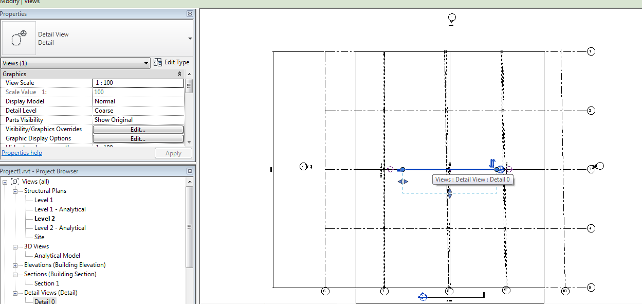
This 'Detail 0' view looks correct. It does cut the floor into a flat rectangular:
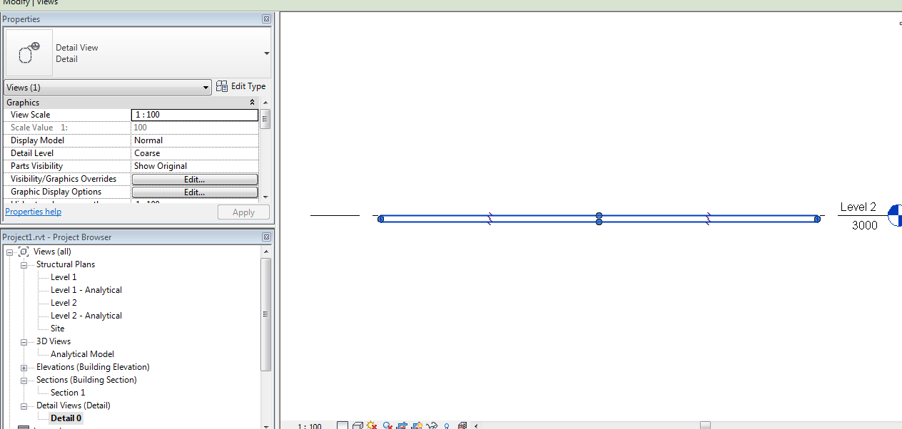
However, when I was query the geometry from this view, the result gives me the whole floor, not just the portion within the view.
I verified this with the following lines of code:
  // Create the 'Details 0' view

  BoundingBoxXYZ boundingBox
    = GetFrontBoundingBox( slab, doc );

  ViewSection viewSection
    = doc.Create.NewViewSection( boundingBox );

  // Retrieve the element geometry within the view;
  // this returns the whole slab (floor)

  Options options = application.Create
    .NewGeometryOptions();

  options.View = viewSection;

  GeometryElement geo1 = slab.get_Geometry(
    options );

  DumpLines( geo1 );

  // Retrieve the geometry of the whole slab;
  // this returns the same result

  GeometryElement geo2 = slab.get_Geometry(
    new Options() );

  DumpLines( geo2 );
Both geo1 and geo2 have exactly the same surface area and volume. They contain exactly the same lines (same end points and length). I must be missing something here.
Question 2: This is not a programming question, rather a usage question. In Revit, how can I show the 'Detail 0' view's bounding box in the 3D views so that I can see its location and size?
Answer 1: Maybe regenerating the model before retrieving the geometry will help?
Answer 2: Maybe you can use the solution suggested to crop a 3D view to a room?
Response: I assume you are talking about the Document.Regenerate method. I tried this method and it got me a bit further.
Now the geometry volume I retrieve is about 1/2 of the floor geometry. It should however be 1/20 as defined by the view boundary. I am pretty sure the view's boundary is 1/20 of the floor as shown in the screen shot above.
  BoundingBoxXYZ boundingBox
    = GetFrontBoundingBox( slab, doc );

  ViewSection viewSection
    = doc.Create.NewViewSection( boundingBox );

  //viewSection.CropBox = boundingBox;

  Options options
    = doc.Application.Create.NewGeometryOptions();

  options.View = viewSection;

  doc.Regenerate();

  GeometryElement geo1 = slab.get_Geometry(
    options );

  DumpLines( geo1 );

  GeometryElement geo2 = slab.get_Geometry(
    new Options() );

  DumpLines( geo2 );
I am not sure whether I should manually set the view CropBox to be the same as the bounding box. I tried that and it seems to give me a totally wrong result. I dumped the edges of geo1 and geo2 to a file and loaded that file into AutoCAD to verify:
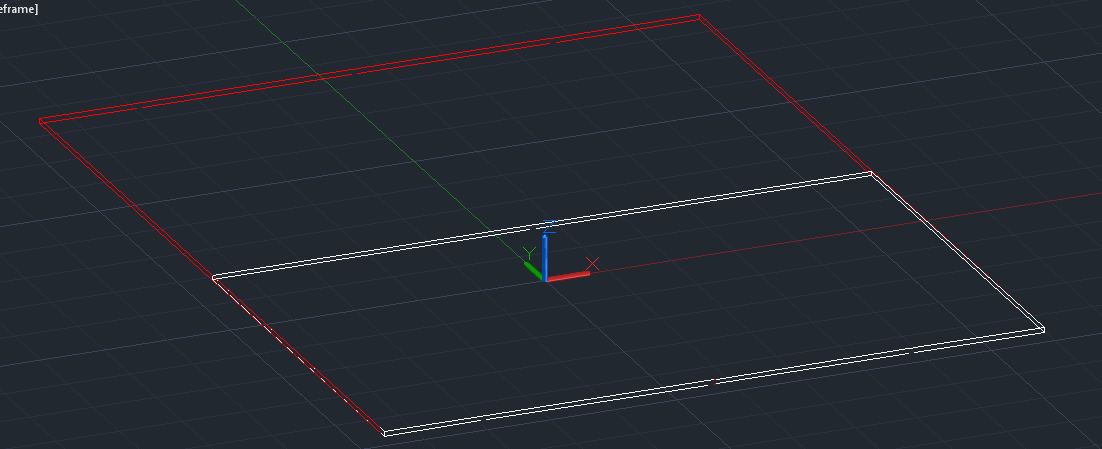
geo1 is indeed half of geo2.
Answer: I thought you are not actually looking for a volume at all, just the cross section.
In that case, you need to eliminate all edges that do not lie exactly in the view plane, and create a boundary loop from the remaining ones that do.
Response: I was originally under the impression that the geometry of an element within a section view would be inside the view's bounding box, as suggested by this image from the Revit Developer Guide:
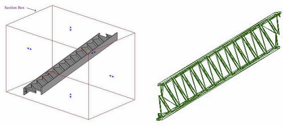
After I checked that assumption using the Revit SDK Object Viewer sample, I realized that the view's location and direction will affect the result of Element.get_Geometry, but the view's bounding box will not. The view will be treated as an infinite plane. This is OK with me. I will just have to manually cut the resulting lines so that they fit within the boundaries.
Many thanks to Bo for this discussion and his efficient research!