Top Faces of Sloped Wall
In the distant past, I discussed retrieving specific floor and wall faces based on their face normal, e.g. the bottom face and boundary of a horizontal floor slab, the exterior face of a vertical wall, and finally the bottom face of a wall.
But what if the normal is not exactly horizontal or vertical?
For instance, how about retrieving the top face of a wall with a sloped profile or the gable wall that we just looked at a few days ago?
That can get a bit complicated, and has an infinite number of solutions. I explore some of them below, with no guarantee that they are anywhere near optimal. In fact, I can guarantee that there are better solutions.
This is prompted by Saikat Bhattacharya, who answered a question on that very issue. In his solution, he also makes use of a couple of new Revit 2012 API methods, for which it is a great pleasure to present such a compelling use case.
- HostObjectUtils – HostObject top, bottom, and side faces: The new methods HostObjectUtils.GetTopFaces, GetBottomFaces and GetSideFaces provide shortcuts to locate the faces of a given roof, floor, or wall which act as the exterior or interior boundary of the object's CompoundStructure. Top and bottom faces are applicable to roofs and floors. Side faces are applicable to walls.
- GetGeometryObjectFromReference – Reference properties: The Reference class was renovated to be more closely aligned with the native Revit class it wraps. GetGeometryObjectFromReference replaces the obsolete GeometryObject property.
- GetGeneratingElementIds – The Element.GetGeneratingElementIds method returns the ids of the elements that generated the input geometry object. The help file provides sample code showing how to use this to find all elements joined or attached to the end faces of a given wall, such as other walls and roofs.
Question: How can I retrieve the top faces of a non-rectangular wall and determine their slopes?
Walls in Revit can have a sloping bottom surface as well as top. A wall can look almost like anything and it is also possible to add arbitrary openings, which complicate things. It seems tricky to find out the right surfaces.
I can imagine I have to look at the wall solid faces and their normals.
However, if the wall has openings such as doors and windows, these objects will affect the faces collection as well. Any idea how to proceed in order to ensure that I identify the correct face or faces that really belong to the top of the wall?
Answer: From what I understand, you wish to find out the faces which are on the top of the wall. If you are analysing something like a gable wall, you expect to have multiple faces on the top of the wall.
There are obviously many different ways of approaching this.
One possible approach is to iterate through each face of the wall and determine its normal vector. Such an approach was used to find the bottom face of a wall. You can extend this to calculate the sloped top faces for your gable wall.
To extract the slope of the top most wall faces, you can start by identifying the wall elevation profile. The approach described accesses each of the faces of a wall and determines the exterior one. On this face, you can access each of the edge loops and determine which edges form the top edges, e.g. by determining the maximum and minimum Z coordinate values using them to calculate the slope.
Another approach could be to access each face of the wall and then go through all of its edges. Using the length of the edge, you can find out the longest edge of a given face. For this longest edge, you can access the start and end point. With these two points for that face, you can use coordinate geometry formula to calculate the slope of the edge. If you happen to know that the wall base and vertical sides are perfectly horizontal and vertical, then the sloped edges all belong to the top of the wall.
Following are the steps that might help in calculating the top faces if there are multiple door/windows on a wall which might also return top faces (and thus confuse with the wall top faces):
- Start with identifying the wall inner or outer face.
- Any given wall has various layers which can be extracted from the compound structure of the wall, and the order of these layers are from the exterior face to the interior. So for example, if a wall has material A in exterior face and then Material B in middle layer and Material C in interior layer, the CompoundStructure property of a wall will return the layers in this order and so the last layer in this will be one which is on the interior face.
- So after we know the material of the interior face of the wall, we can parse through each of the faces of the wall and check which face has which material. When we find a face which has a material that is the same that that of the interior layer, we can know that the face if the interior face. The same approach can be used for finding exterior face too (whichever suits your use case).
- After we find the inner/outer face of wall, we need to identify the top edges of one of the two faces (interior or exterior). You can either use the maximum z value of either of the end points for the edge to identify it or check if the normal on the adjacent faces is a non-zero X, Y or Z with a positive Z value. You can devise your own approach here too.
- Finally you need to collect all the faces that neighbour the top edges and fit the criteria.
In Revit 2012, things are much simpler. The Revit 2012 API provides a new utility class HostObjectUtils with a method GetSideFaces which can be used to obtain the side face of a wall.
From then on, you can follow the approach discussed above, i.e. walk the outer contour of edges of the side face. Find the neighbouring faces, and the face normal returned by Face.ComputeNormal has a positive Z component, it is a top face.
In Revit 2012, you also use the new method GetGeneratingElementIds to find the element ids of the elements that generate the input geometry.
I wrote the following code to demonstrate this approach. It is not yet complete, since we need to add some methods to determine the outer loop, as mentioned in the comments, but it should provide an idea on how you can proceed. You can test this code first with a simple gable wall with no doors or windows and then extend it by adding logic to detect the outer loop returned from face.EdgeLoops.
  IList<Face> topFaces = new List<Face>();

  foreach( Element e in uidoc.Selection.Elements )
  {
    Wall pickedWall = e as Wall;

    // Get the side faces

    IList<Reference> sideFaces
      = HostObjectUtils.GetSideFaces( pickedWall,
        ShellLayerType.Exterior );

    // Access the side face

    Element e2 = doc.GetElement( sideFaces[0] );

    Face face = e2.GetGeometryObjectFromReference(
      sideFaces[0] ) as Face;

    // When there are multiple windows or doors in
    // the wall, we need to find the outer loop
    // that is returned using the face.Edgeloops.
    // For one possible approach to extract the
    // outermost loop, please refer to
    // 0053_2d_polygon_area_outer_loop.htm

    // With the outermost loop, calculate the top faces

    foreach( EdgeArray ea in face.EdgeLoops )
    {
      foreach( Edge edge in ea )
      {
        // For each edge, get the neighbouring
        // face and check its normal

        for( int i = 0; i < 2; ++i )
        {
          Face neighbourFace = edge.get_Face( i );

          XYZ p = edge.Tessellate()[0];

          if( neighbourFace.ComputeNormal(
            new UV( p.X, p.Y ) ).Z > 0 )
          {
            topFaces.Add( neighbourFace );
          }
        }
      }
    }
  }

  int n = topFaces.Count;

  TaskDialog.Show( "Wall Top Faces",
    string.Format( "This wall has {0} top face{1}.",
    n, (1 == n ? "" : "s") ) );
Here is Saikat's detailed explanation of the steps:
- Retrieve the wall we are working with and its side faces, in this case the exterior one.
- Assuming the wall has no windows or doors in it, all the edges of the exterior side faces are part of the outer boundary loop.
- In the case of a rectangular wall, this returns four edges: top, bottom, and two vertical side edges.
- With each edge, say top one, access both the adjoining faces.
- For the top edge, one neighbouring face is the top one and other is vertical and should be the same as the exterior face that we started with.
- For each of the faces, check the Z value of its normal on any point on the edge. I used the Tessellate method to get the points on the edge and calculate the normal at the first point of the edge. One could also use the start point of the edge.
- If the Z value is positive, we know that the face is the top face.
This worked fine for all the test models that I applied it to.
Jeremy adds: Many thanks to Saikat for this research and sample code!
I created a new Building Coder sample command CmdWallTopFaces based on Saikat's code, and before doing so I implemented some support methods in order to easily determine the outermost loop for a wall with openings.
Step one of this process is to implement a simple method to determine the area of an EdgeArray.
Saikat mentioned my implementation to determine the outer loop of a 2D polygon using the method GetSignedPolygonArea.
I also already implemented the method GetPolygonPlane which returns the plane properties of a given 3D polygon placed and oriented arbitrarily in space, i.e. the plane normal, area, and its distance from the origin.
The input polygon for GetPolygonPlane to analyse is provided as a List<XYZ> instance. As you see above, the wall face contour loops are returned from the face Edge|Loops property as EdgeArray instances, so I would like to convert an EdgeArray to a List<XYZ> to easily apply GetPolygonPlane to it.
This is an ideal opportunity to implement an extension method, i.e. a method that I can provide to extend the functionality of the Revit API EdgeArray class in a way that makes it indistinguishable from the EdgeArray native member methods. I created a new class JtEdgeArrayExtensionMethods in the Util.cs module to host the new extension method implementation:
public static class JtEdgeArrayExtensionMethods
{
  /// <summary>
  /// Return a polygon as a list of XYZ points from
  /// an EdgeArray. If any of the edges are curved,
  /// we retrieve the tessellated points, i.e. an
  /// approximation determined by Revit.
  /// </summary>
  public static List<XYZ> GetPolygon(
    this EdgeArray ea )
  {
    int n = ea.Size;

    List<XYZ> polygon = new List<XYZ>( n );

    foreach( Edge e in ea )
    {
      IList<XYZ> pts = e.Tessellate();

      n = polygon.Count;

      if( 0 < n )
      {
        Debug.Assert( pts[0]
          .IsAlmostEqualTo( polygon[n-1] ),
          "expected last edge end point to "
          + "equal next edge start point" );

        polygon.RemoveAt( n - 1 );
      }
      polygon.AddRange( pts );
    }
    n = polygon.Count;

    Debug.Assert( polygon[0]
      .IsAlmostEqualTo( polygon[n - 1] ),
      "expected first edge start point to "
      + "equal last edge end point" );

    polygon.RemoveAt( n - 1 );

    return polygon;
  }
}
With that helper method in place and the existing CmdWallProfileArea.GetPolygonPlane method to determine the area of a 3D polygon, I can easily find the outer loop of a wall which may contain openings like this:
  XYZ normal;
  double area, dist, maxArea = 0;
  EdgeArray outerLoop = null;

  foreach( EdgeArray ea in face.EdgeLoops )
  {
    if( CmdWallProfileArea.GetPolygonPlane(
      ea.GetPolygon(), out normal, out dist, out area )
      && Math.Abs( area ) > Math.Abs( maxArea ) )
    {
      maxArea = area;
      outerLoop = ea;
    }
  }
Now I just need to examine the outer loop to find the wall top faces, and can skip all the others, which are related to openings in the wall:
  // With the outermost loop, calculate the top faces

  foreach( Edge edge in outerLoop )
  {
    // For each edge, get the neighbouring
    // face and check its normal

    for( int i = 0; i < 2; ++i )
    {
      Face neighbourFace = edge.get_Face( i );

      XYZ p = edge.Tessellate()[0];

      if( neighbourFace.ComputeNormal(
        new UV( p.X, p.Y ) ).Z > 0 )
      {
        topFaces.Add( neighbourFace );
      }
    }
  }
}
To test it, I ran my sample command on the walls of the basic sample project included in the Revit installation:

I had to add a few checks to handle exceptional cases. After that, the command generates the following result in the Visual Studio debug output window:
4 top faces found on Walls <117652 Generic - 200>
1 top face found on Walls <117653 Foundation - 305 Concrete>
3 top faces found on Walls <117654 Generic - 200>
2 top faces found on Walls <117685 CORR>
4 top faces found on Walls <117698 CORR>
No side face found for Walls <117714 Storefront>
1 top face found on Walls <117787 Interior - Partition>
1 top face found on Walls <117836 translucent wall>
1 top face found on Walls <117887 Generic - 200>
1 top face found on Walls <117945 Interior - Partition>
2 top faces found on Walls <117963 Interior - Partition>
2 top faces found on Walls <118356 Interior - Partition>
1 top face found on Walls <118454 Generic - 200>
1 top face found on Walls <118547 Interior - Partition>
1 top face found on Walls <118570 Interior - 165 Partition (1-hr)>
1 top face found on Walls <118640 Interior - 165 Partition (1-hr)>
2 top faces found on Walls <123926 CORR>
No side face found for Walls <123967 Storefront>
1 top face found on Walls <124284 Interior - Partition>
1 top face found on Walls <124302 Interior - Partition>
1 top face found on Walls <124405 Interior - Partition>
1 top face found on Walls <124670 CORR>
1 top face found on Walls <127132 Foundation - 305 Concrete>
Skipped Walls FIREPLACE <127491 FIREPLACE>
0 top faces found on Walls <127659 Interior - Partition>
1 top face found on Walls <127660 Interior - Partition>
1 top face found on Walls <127663 Interior - Partition>
0 top faces found on Walls <127941 Interior - Partition>
1 top face found on Walls <128006 Interior - Partition>
No side face found for Walls <132770 Storefront>
1 top face found on Walls <135324 Foundation - 305 Concrete>
1 top face found on Walls <135343 Foundation - 305 Concrete>
1 top face found on Walls <135362 Foundation - 305 Concrete>
1 top face found on Walls <135527 Interior - Partition>
1 top face found on Walls <140108 Interior - Partition>
2 top faces found on Walls <140130 Interior - Partition>
1 top face found on Walls <140190 Interior - Partition>
0 top faces found on Walls <140191 Interior - Partition>
6 top faces found on Walls <140204 Generic - 200>
2 top faces found on Walls <144706 Interior - Partition>
2 top faces found on Walls <144998 CORR>
1 top face found on Walls <145015 CORR>
2 top faces found on Walls <145032 CORR>
1 top face found on Walls <145199 Interior - Partition>
1 top face found on Walls <150987 Generic - 305>
3 top faces found on Walls <151006 Generic - 200>
1 top face found on Walls <151081 Generic - 305>
Anyway, here is the final result reported by this task dialogue message:

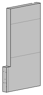
Some of the results in the list above are rather strange, actually... I explored them a bit further and have no explanation so far for the large number of top faces found on some simple walls. For instance, this is the wall '140204 Generic - 200' which is reported to have six top faces in the list above:

The only explanation I can offer for this is that some faces are counted multiple times. One approach to debug this better and try to track down the cause would be to paint the faces like I did for the exterior face of a wall and bottom outer loop of a floor slab.
Another idea that comes to mind is to iterate over the faces instead of the edges. At least that will ensure that no face will be examined more than once.
To identify a face neighbouring the outer side loop, I ended up comparing vertices with each other. Obviously, like all comparisons of real numbers, that requires us to add a fuzz factor, since real-valued coordinates will almost never be exactly equal.
I already implemented an XYZ equality comparer incorporating such a fuzz factor in CmdNestedInstanceGeo.XyzEqualityComparer.
Unfortunately, that equality comparer uses the native Revit API XYZ comparison member method IsAlmostEqualTo, which apparently uses a built-in tolerance that is too fine for our purposes and does not recognise points that we need to identify as equal. I therefore had to implement a new comparer class which takes a given tolerance as an input argument to the constructor, and use a tolerance of 1e-6 instead of the default 1e-9 used internally by Revit, as far as I know:
public class XyzEqualityComparer : IEqualityComparer<XYZ>
{
  double _eps;

  XyzEqualityComparer( double eps )
  {
    Debug.Assert( 0 < eps,
      "expected a positive tolerance" );

    _eps = eps;
  }

  public bool Equals( XYZ p, XYZ q )
  {
    return _eps > p.DistanceTo( q );
  }

  public int GetHashCode( XYZ p )
  {
    return Util.PointString( p ).GetHashCode();
  }
}
That improved things a bit.
One aspect that is somewhat open to interpretation is how to decide whether a face is a top face or not. In some irregularly shaped walls, there may be faces which can be considered either side or top, as you please. I ended up using the following criterion, which allows you to specify a minimum slope of the face normal vector:
  /// <summary>
  /// Minimum slope for a vector to be considered
  /// to be pointing upwards. Slope is simply the
  /// relationship between the vertical and
  /// horizontal components.
  /// </summary>
  const double _minimumSlope = 0.3;

  /// <summary>
  /// Return true if the Z coordinate of the
  /// given vector is positive and the slope
  /// is larger than the minimum limit.
  /// </summary>
  static bool PointsUpwards( XYZ v )
  {
    double horizontalLength = v.X * v.X + v.Y * v.Y;
    double verticalLength = v.Z * v.Z;

    return 0 < v.Z
      && _minimumSlope
        < verticalLength / horizontalLength;
  }
I also ended up implementing the creation of model curve copies of all the top face edges as well, so that the results can be easily visualised and verified. That requires me to open a transaction, which in turn prevents me from using read-only transaction mode, so I encapsulated all the model line creation code within conditional compilation statements like this:
#if CREATE_MODEL_CURVES_FOR_TOP_FACE_EDGES
  [Transaction( TransactionMode.Manual )]
#else
  [Transaction( TransactionMode.ReadOnly )]
#endif // CREATE_MODEL_CURVES_FOR_TOP_FACE_EDGES
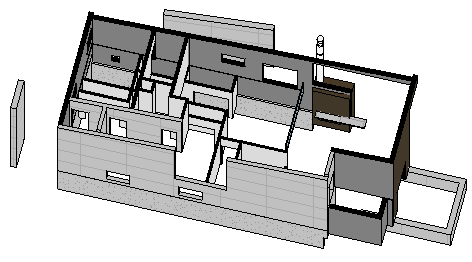
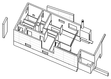
Here is a simplified model that I generated from the basic sample model and used for final testing:

The code now determines 49 top faces for the 45 walls, which is correct, as far as I can tell:

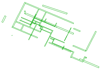
Here are the generated model line copies of the top face edge curves, offset by an inch upwards and isolated in the view:

The final code is a little bit daunting, partly due of the conditional compilation statements:
  UIApplication uiapp = commandData.Application;
  UIDocument uidoc = uiapp.ActiveUIDocument;
  Application app = uiapp.Application;
  Document doc = uidoc.Document;

  Options opt = app.Create.NewGeometryOptions();

  XyzEqualityComparer comparer
    = new XyzEqualityComparer( 1e-6 );

#if CREATE_MODEL_CURVES_FOR_TOP_FACE_EDGES

  Creator creator = new Creator( doc );

  Transaction t = new Transaction( doc );

  t.Start( "Create model curve copies of top face edges" );

#endif // CREATE_MODEL_CURVES_FOR_TOP_FACE_EDGES

  IList<Face> topFaces = new List<Face>();
  int n;

  foreach( Element e in uidoc.Selection.Elements )
  {
    Wall wall = e as Wall;

    if( null == wall )
    {
      Debug.Print( "Skipped "
        + Util.ElementDescription( e ) );
      continue;
    }

    // Get the side faces

    IList<Reference> sideFaces
      = HostObjectUtils.GetSideFaces( wall,
        ShellLayerType.Exterior );

    // Access the first side face

    Element e2 = doc.GetElement( sideFaces[0] );

    Debug.Assert( e2.Id.Equals( e.Id ),
      "expected side face element to be the wall itself" );

    Face face = e2.GetGeometryObjectFromReference(
      sideFaces[0] ) as Face;

    if( null == face )
    {
      Debug.Print( "No side face found for "
        + Util.ElementDescription( e ) );
      continue;
    }

    // Determine the outer loop of the side face
    // by finding the polygon with the largest area

    XYZ normal;
    double area, dist, maxArea = 0;
    EdgeArray outerLoop = null;

    foreach( EdgeArray ea in face.EdgeLoops )
    {
      if( CmdWallProfileArea.GetPolygonPlane(
        ea.GetPolygon(), out normal, out dist, out area )
        && Math.Abs( area ) > Math.Abs( maxArea ) )
      {
        maxArea = area;
        outerLoop = ea;
      }
    }

    n = 0;

    List<XYZ> sideVertices = outerLoop.GetPolygon();

    // Go over all the faces of the wall and
    // determine which ones fulfill the following
    // two criteria: (i) planar face pointing
    // upwards, and (ii) neighbour of the side
    // face outer loop.

    Solid solid = wall.get_Geometry( opt ).Objects
      .OfType<Solid>()
      .First<Solid>( sol => null != sol );

    foreach( Face f in solid.Faces )
    {
      if( f is PlanarFace
        && PointsUpwards( ((PlanarFace)f).Normal ) )
      {
        IList<XYZ> faceVertices
          = f.Triangulate().Vertices;

        //if( sideVertices.Exists( v
        //  => faceVertices.Contains<XYZ>( v, comparer ) ) )
        //{
        //  topFaces.Add( f );
        //  ++n;
        //}

        foreach( XYZ v in faceVertices )
        {
          if( sideVertices.Contains<XYZ>(
            v, comparer ) )
          {
            topFaces.Add( f );
            ++n;

#if CREATE_MODEL_CURVES_FOR_TOP_FACE_EDGES

            // Display face for debugging purposes

            foreach( EdgeArray ea in f.EdgeLoops )
            {
              IEnumerable<Curve> curves
                = ea.Cast<Edge>()
                  .Select<Edge, Curve>(
                    x => x.AsCurve() );

              foreach( Curve curve in curves )
              {
                creator.CreateModelCurve(
                  curve.get_Transformed( _t ) );
              }
            }

#endif // CREATE_MODEL_CURVES_FOR_TOP_FACE_EDGES

            break;
          }
        }
      }
    }

    Debug.Print( string.Format(
      "{0} top face{1} found on {2}",
      n, Util.PluralSuffix( n ),
      Util.ElementDescription( e ) ) );
  }

#if CREATE_MODEL_CURVES_FOR_TOP_FACE_EDGES
  t.Commit();
#endif // CREATE_MODEL_CURVES_FOR_TOP_FACE_EDGES

  n = uidoc.Selection.Elements.Size;

  string s = string.Format(
    "{0} wall{1} selected",
    n, Util.PluralSuffix( n ) );

  n = topFaces.Count;

  TaskDialog.Show( "Wall Top Faces",
    string.Format(
      "{0} with {1} top face{2}.",
      s, n, Util.PluralSuffix( n ) ) );

  return Result.Succeeded;
Some obvious improvements to this algorithm immediately spring to mind. For instance, I could check the list of side face outer loop vertices and eliminate all the ones which lie exactly below some other one. In the simplest and most common case of a rectangular wall, that would eliminate the two bottom vertices and just leave the two top ones, halving their number. That is left as an exercise to the reader.
I hope you find this as interesting and satisfying as I do and look forward to hearing about further uses that you find for both the new Revit API methods and my various extensions. I also look forward very much to hearing about your more effective solutions to this problem.
Here is version 2012.0.89.0 of The Building Coder samples including the new command CmdWallTopFaces.