Blends, Hermite Splines and Derivatives
Here are some pretty exciting observations by Ritchie Jackson of the Adaptive Architecture and Computation programme at UCL, the University College London, on blends and Hermite splines:
Blends, Hermite Splines & Derivatives: Some Observations
Thanks for all the helpful code on your site – as I'm teaching myself to use the Revit API I've found the information invaluable. I'm doing an MSc. Adaptive Architecture and Computation at UCL, London and will be using Revit for my dissertation.
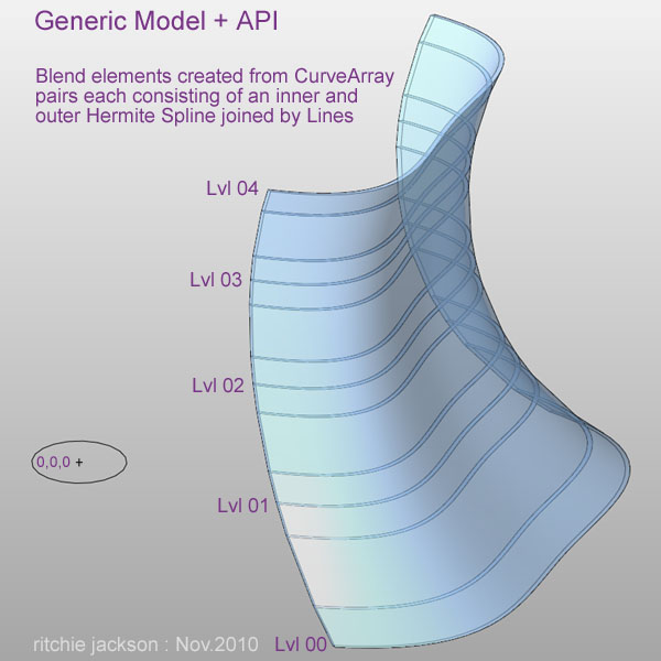
The discussion of the NewBlend method prompted me to attach a few screenshots. I've been using Blends driven by 2D Hermite splines created within a generic model family to test facade options. Interestingly, the API documentation states that "In Revit you cannot create a Hermite curve but you can import it from other software such as AutoCAD" – which seems to be partially erroneous.
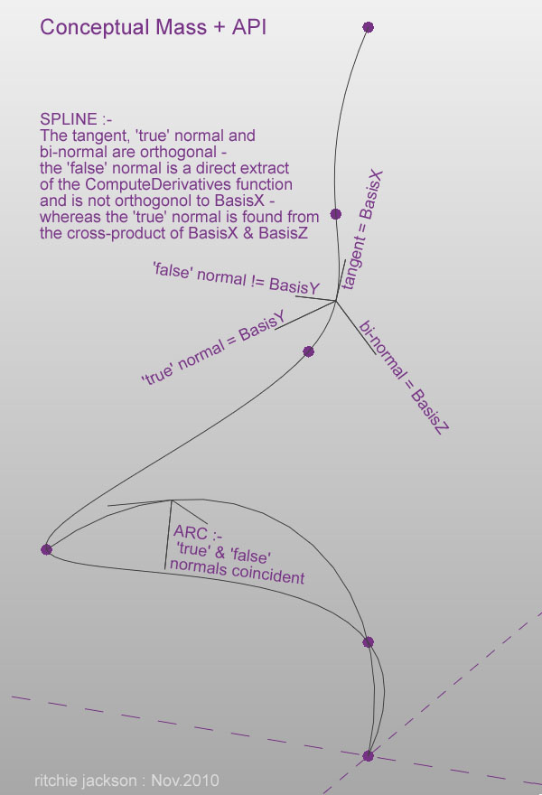
In conjunction with this I was interested in placing geometry on a 3D Hermite spline using the ComputeDerivatives function to extract the moving frame. There seems to be an issue with the BasisY component which is meant to yield the normal vector via the second derivative. This only appears to work with arcs and not with splines. In the latter case the 'normal' points roughly in the direction of the second derivative (Van Verth, Bishop, 2008: "Essential Mathematics for Games and Interactive Applications") so it should be found by computing the cross-product of the tangent vector (BasisX) and the bi-normal (BasisZ). That is, the 'BasisY' component provided by ComputeDerivative appears to be incorrect:

Here is a piece of working code which illustrates the above issue, spline_test_01_mass.cs. It implements a class called by an Application Macro from within a metric conceptual mass family. It would seem that 'CurveByPoints' and 'HermiteSpline' are one and the same thing as their moving frames are superimposed.
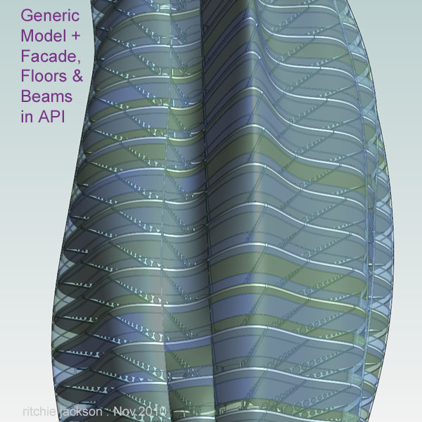
Here is an image taken from a work-in-progress investigating the potential for creating geometry entirely via the API within a generic model family. Although the functions are more limited in comparison to the conceptual mass families, they are not too restrictive:

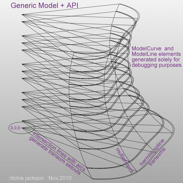
The following images demonstrate how the facade elements were constructed. Whilst the mullions are comprised of arcs for simplicity's sake, Hermite splines may be used to provide more variation:

Model line and curve elements have been generated for geometric form generation debugging purposes, and additional intersection lines are used to generate the transom setouts.
Here are the blend elements created from CurveArray pairs, each consisting of an inner and outer Hermite spline joined by lines:

Very many thanks to Ritchie for providing these exciting insights and examples!
If you are interested in more examples like this, please post a comment to let us know.