Cable Tray Orientation and Fittings
Here is an extra long post, seeing as I will be occupied with a training course the coming two days.
In the overview of the Revit MEP 2011 API, I mentioned that new elements have been introduced to represent cable trays and conduits.
We already had a look at the creation of new conduit elements in the pipe to conduit converter.
The creation of cable tray elements is equally simple, making use of the static Create method on the CableTray class.
This is another example of the new element creation paradigm instead of the creation document classAutodesk.Revit.Creation.Document, a second generation API automatically generated with RIDL, the Revit Interface Definition Language.
In order to automatically create a whole cable tray run, however, we need both the straight segment cable tray elements and also the fittings to connect them with each other, elbows to turn corners and branching elements to represent junctions.
This is harder to implement for cable trays than for conduits, because the former have a rectangular cross section. To connect a horizontal cable tray segment with a vertical one requires the latter to be precisely oriented so that the elbow will line up properly with both. This is simpler for conduits, which have a round cross section.
This led to the following questions and exhaustive exploration of cable tray fittings and orientation:
Question: We are trying to create cable tray objects through API. When we create them manually, the joints (cable tray fittings) are automatically created. How can we achieve this programmatically?
Answer: The situation for cable trays is the same as for duct and pipe elements, i.e. it is up to the application to explicitly create the fittings in between the segments as it sees fit.
There is no way to auto-generate the fittings. You can however use the fitting APIs to create cable tray fittings yourself. For example, NewElbowFitting, NewTeeFitting, NewTransitionFitting, NewCrossFitting, should all produce valid cable tray fittings when connected to valid cable tray objects.
You can create a fitting to join two connectors (at end of cable tray) by calling the Revit.Creation.Document.NewXyxFitting methods such as NewElbowFitting, NewTeeFitting etc. Each end of the cable tray segment has a connector. These methods take the connectors as input arguments. To use them, you can implement the following steps:
- Retrieve the connectors belonging to the cable tray, e.g. via cableTray.ConnectorManager.Connectors.
- Determine a pair of connectors which should be connected, for instance by checking their position, connector type, or something else.
- Call the appropriate NewXyzFitting method to create the Fitting element to join the connectors.
The AutoRoute and AvoidObstruction Revit SDK samples demonstrate some uses of the new fitting methods.
This explanation immediately leads to the next question:
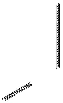
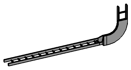
Question: When we create cable tray objects programmatically, they always appear parallel to X axis, like this:
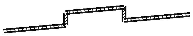
This is the result of some initial test code that creates individual cable tray elements, but no fittings. It naively creates the cable trays one by one using CableTray.Create, and as you can see that does not generate the fittings nor rotate the trays into the right position relative to each other either.
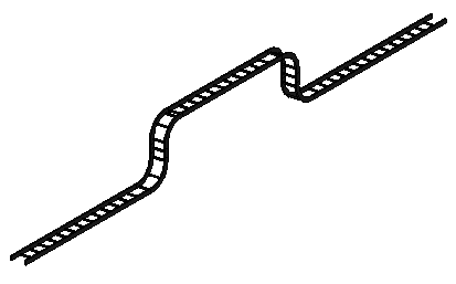
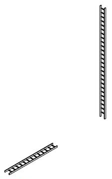
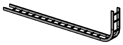
When we create them manually through the user interface, the cable trays automatically rotate to line up with their predecessor element, and the appropriate fittings are added to connect them:
How can we achieve this through the API, please? What is the correct way to programmatically create a run of connected cable trays, i.e. add fittings and correct relative positions? Can you provide a sample that shows how to do this?
Answer: As said, you can simply use the New*Fitting methods to place the fittings between runs. However, I assume that the application has to ensure that the alignment and correct orientation is set up before they can create the fitting to connect properly.
I initially tried to use the following code based on the ideas used in the AutoRoute SDK sample, but it does not work as expected:
  ElementId idType = new ElementId( 411325 );
  ElementId idLevel = new ElementId( 311 );

  XYZ start1 = new XYZ( -30.49, 38.42, 10.05 );
  XYZ end1 = new XYZ( -20.43, 30.83, 10.05 );
  CableTray tray1 = CableTray.Create(
    doc, idType, start1, end1, idLevel );

  XYZ start2 = new XYZ( -20.43, 30.83, 10.05 );
  XYZ end2 = new XYZ( -20.43, 30.83, 13.33 );
  CableTray tray2 = CableTray.Create(
    doc, idType, start2, end2, idLevel );

  Connector c1start, c1end = null;

  foreach( Connector c in
    tray1.MEPSystem.ConnectorManager.Connectors )
  {
    if( c.Origin.IsAlmostEqualTo( start1 ) )
    {
      c1start = c;
    }
    else if( c.Origin.IsAlmostEqualTo( end1 ) )
    {
      c1end = c;
    }
  }

  Connector c2start = null, c2end;

  foreach( Connector c in
    tray2.MEPSystem.ConnectorManager.Connectors )
  {
    if( c.Origin.IsAlmostEqualTo( start2 ) )
    {
      c2start = c;
    }
    else if( c.Origin.IsAlmostEqualTo( end2 ) )
    {
      c2end = c;
    }
  }

  if( null != c1end && null != c2start )
  {
    doc.Create.NewElbowFitting( c1end, c2start );
  }
The first reason it does not work is that the cable tray MEPSystem property is null, so the connectors cannot be found. Instead, the cable tray element has its own ConnectorManager property, which provides access to the required connectors.
After modifying the code to use that and adding the call to connect the two connectors, it succeeds, but the call to insert the elbow fitting still fails. Also, if I skip that call, the cable tray is still not rotated so that it matches up with its connected neighbour, even if the connectors are successfully connected:
  Connector c1start, c1end = null;

  foreach( Connector c in
    tray1.ConnectorManager.Connectors )
  {
    if( c.Origin.IsAlmostEqualTo( start1 ) )
    {
      c1start = c;
    }
    else if( c.Origin.IsAlmostEqualTo( end1 ) )
    {
      c1end = c;
    }
  }

  Connector c2start = null, c2end;

  foreach( Connector c in
    tray2.ConnectorManager.Connectors )
  {
    if( c.Origin.IsAlmostEqualTo( start2 ) )
    {
      c2start = c;
    }
    else if( c.Origin.IsAlmostEqualTo( end2 ) )
    {
      c2end = c;
    }
  }

  if( null != c1end && null != c2start )
  {
    c1end.ConnectTo( c2start );

    // this throws
    // Autodesk.Revit.Exceptions
    // .InvalidOperationException:
    // "failed to insert elbow".

    doc.Create.NewElbowFitting( c1end, c2start );
  }
The call NewElbowFitting which is used in the AutoRoute sample throws the exception "failed to insert elbow".
I see that you are testing with cable tray elements, which may be adding geometrical complications to getting the test code right. I would suggest trying the same code using conduit elements first, since they have a simpler geometry shape. For example, the conduit probably does not care which direction is "up", etc. Also, another idea would be to draw some geometry using the user interface and analyse that. For example, lay out a run including pipe, elbow, and pipe, then extract the coordinates from it and try to recreate it through API. That way you will know the geometry is possible to create, the radius and ends points for the elbow are "correct", etc.
From the initial exploration, we see that an application wishing to create a complete connected cable tray run will have to ensure that the cable trays are correctly aligned and also connect them with each other.
The AutoRoute and AvoidObstructions Revit SDK samples provide a useful starting point, showing how to create a connected mechanical HVAC duct system and pipe deviations around obstructions. Similar principles apply for cable trays as well. The main differences between duct and cable tray are:
- Cable tray has no system.
- Cable tray and fittings have specific orientations.
One needs to manually place and orient cable trays in the proper locations before creating the fittings between them. The connections can be created regardless, however.
In the AutoRoute sample, the method CreateDucts calls the Revit API method NewDuct. It inserts a new duct element into the model and returns its two connectors at the end points. After creating the individual duct elements, the connectors are hooked up with each other using methods like
  m_document.Create.NewElbowFitting(
    connectors[2], baseConn2 );
The duct connectors are retrieved through their MEPSystem property and its connector manager, which returns the connector set.
In the case of cable trays, the MEPSystem property is null, so it cannot be used to retrieve the connectors. Happily, they have their own connector manager property themselves, so there is no need to go through the MEPSystem property.
When I tried to connect the cable trays in a manner similar to the ducts in the AutoRoute sample, an exception was thrown:
  Autodesk.Revit.Exceptions.InvalidOperationException:
    "failed to insert elbow".
During the further analysis of how to set up the cable trays appropriately to insert the fittings, one initial idea was that one should not be connecting the two connectors for the two items directly, but foreshortening them so that the connector can be properly inserted, e.g. leaving some space for the fittings. E.g., if the elbow radius is 6', the end of the first tray should be 6' away from the nominal intersection point, and the start of the second one as well, so that the elbow fits into the gap.
The AutoRoute sample does indeed cut back the ducts by a certain distance:
private const double min1FittingLength = 1;
As we shall see below, however, this is not required for conduits and cable trays.
When exploring the orientation of the cable trays in more depth, the next question was how to know what the correct orientation is, and how to set it once it is known?
One can look at the cable tray's connectors, either the property 'Angle' or some part of 'CoordinateSystem', to determine its orientation.
It also looks like some of the content is built 'on its side':
There are separate fittings for the various bends in the 'Conduit Type' definition:

Looking at the Vertical Outside family, it is 'on its side', and would need to be rotated 90 degrees on the 'front/back' axis. One still needs to figure out if that is +90 or -90:
There may be more rules used to orient content. They can be determined by inspecting the various bend families.
To continue with the topic of connecting the cable tray segments:
For testing purposes, it is significantly easier to start exploring the issue with conduit instead of cable tray elements. Connecting the conduits is simpler, because they have no orientation, being symmetrical.
It does not appear that the Conduit or CableTray elements care about the "foreshortening" or "lengthening" of the objects to get a proper fit. The main issue is that the objects have to be "oriented" correctly, otherwise Revit issues a message indicating it is not correct. Basically, it cannot create a proper fitting due to alignment.
I started by testing creating conduit runs using objects that were all created in the same level plane. This works fine with no additional orientation required and shows that the lengthening and shortening is performed automatically as required to make a good fit. The command CmdConduit in the attached sample code demonstrates this.
I then moved to cable tray and that also worked with the same simple test data used for the conduits, only switching to creating cable trays instead. An example in the plane is provided by the sample command CmdCableTray2.
The problem comes when creating the cable trays in different planes, because then the cable trays are not oriented appropriately well by default by the creation methods, and there is no way to specify something like an "up" normal during creation.
So it started by looking like this where the second one going "up" is not well oriented to make a fitting:
Then in the code I "rotated" the location property to align it with the first one:
Once it was "aligned", the fitting connected it with no further problems. In fact, the cals made by CmdCableTray3 automatically provide the proper shortening and lengthening as required to make the fitting work:
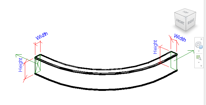
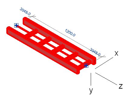
Looking in more detail at the orientation of the cable trays relative to each other, we see that access to their coordinate systems is provided by the CoordinateSystem property on the Connector object. For the ladder cable tray, it seems that the connector coordinate system Z axis points straight out of the cable tray, parallel to its location line. The X axis points to the left hand side of the cable tray, and the Y axis points down:
So, for instance in order to create a 'flat' or 'sideways' elbow between two cable trays lying in the XY plane, you need to ensure that both of their connector Y axes are vertical.
With the Z axis of the connector coordinate system pointing straight out of the tray, and the Y axis perpendicular to the direction of the ladder rungs, in order to create an elbow between a cable tray lying in the XY plane with a vertical one, one has to rotate the vertical tray so that the Y axis of its end connector is aligned with the Z axis of its predecessor's starting connector:
  Transform t1 = c1end.CoordinateSystem;
  Transform t2 = c2start.CoordinateSystem;

  double angle = t2.BasisY.AngleOnPlaneTo(
    t1.BasisZ, XYZ.BasisZ );

  Line axis = app.Create.NewLineUnbound(
    start2, XYZ.BasisZ );

  tray2.Location.Rotate( axis, angle );

  c1end.ConnectTo( c2start );

  doc.Create.NewElbowFitting( c1end, c2start );
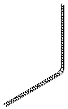
The sample command CmdCableTray4 finally produces the following, which is exactly what we are aiming for:
One can also cause a direction swapping fitting to be created by rotating the vertical tray so that its start connector X axis is aligned with the predecessor direction:
  double angle = t2.BasisX.AngleOnPlaneTo(
    t1.BasisZ, XYZ.BasisZ );
This results in this direction swapping fitting:
Here is the entire CableTray source code and the Visual Studio solution used to create each of the examples discussed above. Each is implemented in its own separate command class. It also includes a cleaned up version of the initial code:
- CmdCableTray – initial sample code.
- CmdConduit – connecting conduits in the XY plane.
- CmdCableTray2 – connecting cable trays in the XY plane.
- CmdCableTray3 – connecting cable trays outside the XY plane.
- CmdCableTray4 – connecting the first 'twisted' cable trays from the initial sample code.