Pipe to Conduit Converter
I am pretty busy right now, both with day-to-day work answering cases and preparing training material, and also preparing for upcoming events. These include:
- Revit Programming Webcast on May 20 (register).
- DevCamp conference on June 7-9.
- DevLabs in Waltham, USA, on June 10-11 (register).
- DevLabs in Munich, Germany, on June 21-25 (register).
- Autodesk University ... still far away in the future, but some preparations already have to be made.
- Lots and lots of vacation this summer!
Due to all that and because I keep discovering new exciting and surprising things to write about every single day, I have neglected to publish this nice article that I have had lying around for quite a while now, actually almost two months.
A number of the topics that I address below have already been covered, both by me and others, but this is probably the most succinct and complete coverage that you will find anywhere in one single piece.
In any case, this should give you enough reading material to digest over the coming weekend as well as a nice little end user utility.
Pipe to Conduit Converter
My First Revit 2011 Add-In
Abstract
The Revit 2011 pipe to conduit converter add-in p2c presented in this article is of interest in two respects:
- It implements a useful utility for converting pipes to conduits.
- It presents an opportunity to discuss many aspect of the new API functionality.
If you are interested in this utility for the sake of using it, look no further. The binary executable is available for download right here. So is the source code, and so is this text that you are reading, nicely formatted in RTF:
- Binary executable p2c.dll and its add-in manifest PipeToConduitConverter.addin.
- Complete source code and Visual Studio solution.
- This text in rich text format RTF.
Pipes and Conduits
Some of the main new product features in Revit MEP 2011 are the support for conduits, cable trays and panel schedules.
In previous versions, many users used pipes to represent the missing conduit elements. With the introduction of native conduit elements in Revit MEP 2011, it makes sense to convert the legacy models to the new format. The pipe to conduit converter p2c prompts the user to select existing pipe elements and automatically converts them to conduits.
Command Implementation Overview
There are two nice aspects of the p2c implementation which make it interesting to discuss as an introductory example to programming a Revit 2011 add-in:
- The implementation is very short and sweet.
- A large number of new API features are used.
The short and sweet aspect stems from the fact that it does very little. In fact, it simply converts certain user-selected pipes to conduits, i.e. reads the pipe location and dimensions, generates corresponding conduit elements, and deletes the original pipes.
As a last additional feature, I added code to read the pipe diameter and transfer that to the conduit replacing it. But that really is all it does.
The amount of new API functionality that we are able to make use of in this short sample is really quite surprising. In less than two hundred lines of code, the following new and updated API features are used:
Contents
- Revit API assembly split
- Namespace reorganisation
- Command registration manifest
- External command Execute method and attributes
- Transaction mode
- Regeneration option
- Task dialogues for user messages
- Interactive filtered element selection
- Redesigned element filtering
- New element creation paradigm
- Access to pipe and conduit sizes
Revit API Assembly Split
The Revit API was previously provided through one single .NET assembly named RevitAPI.dll and located together with Revit.exe and Revit.ini in the Program subdirectory of the main Revit installation folder. It has now been split into two separate assemblies, RevitAPI.dll and RevitAPIUI.dll. The former now contains only methods used to access Revit's application, documents, elements, and parameters at the database level, whereas the latter defines the interfaces related to manipulation and customization of the Revit user interface.
Almost all Revit add-ins will need to reference both of these, and so does p2c. As always, when referencing these, remember to set the 'Copy Local' flag to false.
To provide access to application and document level interfaces from both assemblies, the Application and Document classes have also been split into two:
- Autodesk.Revit.UI.UIApplication provides access to UI-level interfaces for the application such as adding a ribbon panels to the user interface and accessing the active document in the user interface.
- Autodesk.Revit.ApplicationServices.Application provides access to all other application level properties.
- Autodesk.Revit.UI.UIDocument provides access to UI-level interfaces for the document, such as the contents of the selection and the ability to prompt the user to make selections and pick points.
- Autodesk.Revit.DB.Document provides access to all other document level properties.
The ExternalCommandData interface now provides access to the UIApplication object as well as the active view. From the active UIApplication object you can obtain the active UI document. You can also construct the UIApplication from the Application object, and the UIDocument from the DB level document at any time.
Namespace Reorganisation
The Revit API namespaces have been renamed and rearranged to be more consistent and more suitable for future expansion. In previous releases, many API classes were split along the lines of functionality and Revit vertical product, which led to confusion about the location of element and symbol classes for the various flavours of Revit. In the new namespace structure, there is a primary division into three sets of namespaces:
- Autodesk.Revit.ApplicationServices: settings and options for the main Revit application.
- Autodesk.Revit.DB: access to Revit database data.
- Autodesk.Revit.UI: access to and customisation of the Revit user interface.
These main namespaces can include subdivisions based on discipline, e.g.
- Autodesk.Revit.DB.Architecture
- Autodesk.Revit.DB.Electrical
- Autodesk.Revit.DB.Mechanical
- Autodesk.Revit.DB.Plumbing
- Autodesk.Revit.DB.Structure
Classes useful in more than one discipline are placed in the Autodesk.Revit.DB main namespace.
Less commonly used classes, like event arguments, may also be placed in subordinate namespaces, such as
- Autodesk.Revit.DB.Events
- Autodesk.Revit.UI.Events
As a result of the rearrangement of the namespaces, a few classes have been modified more drastically than simply being moved to new namespaces:
- Autodesk.Revit.Geometry.Element is renamed to Autodesk.Revit.DB.GeometryElement to avoid a naming conflict.
- Autodesk.Revit.Geometry.Instance is renamed to Autodesk.Revit.DB.GeometryInstance to avoid a naming conflict.
- Autodesk.Revit.Structural.Enums.Material is renamed to Autodesk.Revit.DB.MaterialType to avoid a naming conflict.
- Autodesk.Revit.Options.Application has been removed. The properties accessible from this class have been moved into Autodesk.Revit.ApplicationServices.Application.
A full list mapping the changes is provided in the Revit SDK document "Revit 2011 API Namespace Remapping.xlsx".
In p2c, we make use of the following namespaces:
#region Namespaces
using System;
using System.Diagnostics;
using System.Collections.Generic;
using Autodesk.Revit.Attributes;
using Autodesk.Revit.DB;
using Autodesk.Revit.DB.Electrical;
using Autodesk.Revit.DB.Plumbing;
using Autodesk.Revit.UI;
using Autodesk.Revit.UI.Selection;
using InvalidOperationException
  = Autodesk.Revit.Exceptions
    .InvalidOperationException;
#endregion // Namespaces
Command Registration Manifest
P2c makes use of the new command registration facility based on add-in manifest files. This approach significantly simplifies the installation of an add-in, since there is no longer any need to edit the Revit.ini file. The add-in manifest files make it easier to share and customise the configuration of add-ins and provide much finer control of the loading process and additional options.
Manifest files are XML files. They are read automatically by Revit when they are placed in one of two locations on a user's system. There are separate locations for individual users or all users, and they also depend on whether you are running Windows XP or Vista/Windows 7. For a specific user, the files are located in
- C:\Documents and Settings\
\Application Data\Autodesk\Revit\Addins\2011 for Windows XP, and - C:\Users\
\AppData\Roaming\Autodesk\Revit\Addins\2011 for Vista/Windows 7. - C:\Users\
The non-user specific location is in
- C:\Documents and Settings\All Users\Application Data\Autodesk\Revit\Addins\2011 for Windows XP, and
- For Vista/Windows 7 - C:\ProgramData\Autodesk\Revit\Addins\2011 for Vista/Windows 7.
All files with an extension of .addin found in these locations will be read and processed by Revit during start-up. Multiple add-ins may be loaded by a single manifest file. The manifest file syntax defines tags allowing you to specify all the information previously defined in the Revit.ini registration data, i.e. assembly path, full class name, text and description:
- Assembly: The full path to the add-in assembly file.
- FullClassName: The full name of the class in the assembly file which implements IExternalCommand or IExternalApplication.
- Text: The name of the button for an external command.
- Description: Short description of the command, used as the button tooltip.
It also supports a long list of other new functionality:
- ClientId: A GUID which represents the id of this particular application.
- Name: The name of application. Required; for ExternalApplications only.
- VisibilityMode: Provides the ability to specify if a command is visible in project documents, family documents, or no document at all. Also provides the ability to specify the discipline(s) where the command should be visible. Multiple values may be set for this option. By default, a command is available in all modes and disciplines, including when there is no active document.
- AvailabilityClassName: The full name of a class in the assembly file implementing IExternalCommandAvailability. This class allows a command to be selectively grayed out depending on context.
- LargeImage: The path to the command button icon to display in the External Tools pull-down menu.
- LongDescription: Long description of the command, used as part of its extended tooltip. This tooltip is shown when the mouse hovers over the command for a long amount of time. You can split the text of this option into multiple paragraphs by placing <p> tags around each paragraph.
- TooltipImage: The path to an image file to show as a part of the button extended tooltip.
- LanguageType: Localization setting for Text, Description, LargeImage, LongDescription, and TooltipImage of external tools buttons. Revit will load the resource values from the specified language resource dll. The value can be one of the eleven languages supported by Revit.
As you can see, there is a large amount of very useful new functionality buried in here! For full details, especially on localisation, external command accessibility and the IExternalCommandAvailability interface, please refer to the "Revit Platform API Changes and Additions.doc" document provided in the Revit SDK.
The Revit.ini registration mechanism remains in place for the 2011 release but will be removed in the future. The Revit.ini mechanism does not offer any of the new capabilities listed above.
As an example of a pretty minimal add-in manifest file, here is the one for our p2c command:
<?xml version="1.0" encoding="utf-8" standalone="no"?>
<RevitAddIn>
  <AddIn Type="Command">
    <Text>Convert Pipes to Conduits</Text>
    <Description>Convert Pipes to Conduits</Description>
    <Assembly>C:\src\p2c\p2c\bin\Debug\p2c.dll</Assembly>
    <FullClassName>p2c.Command</FullClassName>
    <ClientId>835d6ad1-1a99-4039-95dc-e752ff635928</ClientId>
  </AddIn>
</RevitAddIn>
As said, installation is now significantly simplified, since all you have to do is copy the add-in assembly to your hard disk, update the assembly path specified in the manifest file, and copy the manifest file to the desired location where Revit can pick it up without affecting any other existing functionality or touching any Revit files or other parts of the Revit installation.
External Command Execute Method and Attributes
As before, the external command class needs to fulfil the IExternalCommand interface, which requires it to implement the Execute method. The Execute method signature is virtually unchanged from the Revit 2010 API, except that the command result enumeration is now moved to Autodesk.Revit.UI.Result. The new API does require you to set two attributes on the command class, though, to define its
- Transaction mode and
- Regeneration option.
Transaction Mode
In previous versions of the Revit API, the transaction mode was rigorously predefined by the framework, more or less like the new automatic mode. In Revit 2011, an add-in can decide for itself how transactions should be set up for it. The new TransactionMode attribute must be applied to the IExternalCommand implementation class to control transaction behaviour. It controls how the API framework expects transactions to be used when the command is invoked and supports the following three values:
- TransactionMode.Automatic: The framework creates a transaction on the active document before the external command is executed. The transaction is committed or rolled back after command completion based upon the return value of the Execute method. A command cannot create and start its own Transactions, but it can create SubTransactions as required.
- TransactionMode.Manual: The framework will not create a transaction, but it will create an outer group to roll back all changes if the external command returns a failure status. Instead, you may use combinations of Transactions, SubTransactions, and TransactionGroups as you please. You will have to name your transactions, which will then appear in the Undo menu.
- TransactionMode.ReadOnly: No transaction or group will be created automatically, and no own transactions may be created for the lifetime of the command. The command may only read from the model, not write anything to it.
In all three modes, the TransactionMode specified only applies to the active document. You may open other documents during the course of the command, and you have complete control over the creation and use of Transactions, SubTransactions, and TransactionGroups on those other documents, even in ReadOnly mode.
For quick porting of existing legacy commands, the automatic mode is obviously the closest to the old behaviour, and that is also the mode that we apply to the p2c command.
Regeneration Option
The new RegenerationAttribute must be applied to external application and command implementation classes to control their regeneration behaviour. This mode controls whether or not the API framework automatically regenerates after every model modification. There are two supported values:
- RegenerationOption.Automatic: The framework regenerates after every change to the model. This is equivalent to the behaviour in Revit 2010 and earlier. Regeneration and update can be suspended using SuspendUpdating for some operations, but in general the performance of multiple modifications within the same file will be slower than when using the manual regeneration option. This mode is obsolete and provided for backwards compatibility only. It will be removed in a future release.
- RegenerationOption.Manual: The API framework will not regenerate after every model level change. Instead, you may use the regeneration APIs to force update of the document after a group of changes. SuspendUpdating blocks are unnecessary and should not be used. Performance of multiple modifications of the Revit document is faster than using automatic regeneration. Since this mode suspends all updates to the document, your application should not read data from the document after it has been modified until after it has been regenerated, otherwise it will be accessing stale data. This mode will be the only option in a future release.
The regeneration mode used for an event or updater call-back is the same as the mode of the external application or command which registered it.
In addition, two new document methods have been added to allow an application running in manual regeneration mode to update Revit document elements at any time:
- Document.Regenerate
- Document.AutoJoinElements
P2c uses the manual regeneration mode.
Command Class Implementation
To demonstrate the use we make of the new attributes and the access to the UI and DB document instances, here is the skeleton of the p2c external command implementation:
  [Transaction(TransactionMode.Automatic)]
  [Regeneration(RegenerationOption.Manual)]
  public class Command : IExternalCommand
  {
    public Result Execute(
      ExternalCommandData commandData,
      ref string message,
      ElementSet elements )
    {
      Result result = Result.Failed;

      UIApplication app = commandData.Application;
      UIDocument uidoc = app.ActiveUIDocument;
      Document doc = uidoc.Document;

      try
      {
        // ... main implementation goes here ...

        result = Result.Succeeded;
      }
      catch( InvalidOperationException )
      {
        // selection cancelled

        result = Result.Cancelled;
      }
      catch( Exception ex )
      {
        // if any error occurs, display error
        // information and return failed

        message = ex.Message;
      }
      return result;
    }
  }
Task Dialogues for User Messages
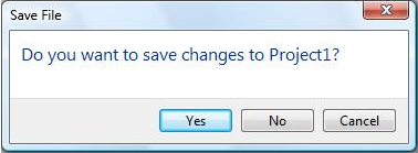
The API now offers the ability to create and display Revit-style task dialogues. It provides capabilities similar to the System.Windows.Forms.MessageBox with a Revit look-and-feel, like this:
To make use of it, you can construct an instance of the TaskDialog class and use its members to set the instructions, detailed text, icons, buttons and command links to be displayed. The class also provides a static shortcut method Show offering a quick way to show minimal task dialogue without explicitly instantiating it.
P2c makes use of both methods in the following utility methods:
  const string _caption = "Pipe to Conduit Converter";

  #region Formatting and message handlers
  /// <summary>
  /// MessageBox or Revit TaskDialog
  /// wrapper for informational message.
  /// </summary>
  public static void InfoMsg( string msg )
  {
    Debug.WriteLine( msg );

    TaskDialog.Show( _caption, msg,
      TaskDialogCommonButtons.Ok );
  }

  /// <summary>
  /// MessageBox or Revit TaskDialog
  /// wrapper for error message.
  /// </summary>
  public static void ErrorMsg( string msg )
  {
    Debug.WriteLine( msg );

    TaskDialog d = new TaskDialog( _caption );
    d.MainIcon = TaskDialogIcon.TaskDialogIconWarning;
    d.MainInstruction = msg;
    d.Show();
  }
  #endregion // Message handlers
Interactive Filtered Element Selection
The Revit 2010 API and previous versions provided some very rudimentary element picking facilities, and none at all for selecting other objects such as a point on the graphics screen or sub-entities such as a face or an edge within a building element. This has changed radically in Revit 2011.
This application has some very basic element selection requirements. The current implementation prompts the user to select a set of pipes to be converted. Generic element picking within an add-in is achieved using the PickObjects method. It comes in several overloads, taking the following lists of arguments:
- ObjectType: prompts the user to select multiple objects.
- ObjectType, string: prompts the user to select multiple objects while showing a custom status prompt string.
- ObjectType, ISelectionFilter: prompts the user to select multiple objects which pass a customer filter.
- ObjectType, ISelectionFilter, string: prompts the user to select multiple objects which pass a custom filter while showing a custom status prompt string.
- ObjectType, ISelectionFilter, string, IList of Reference: prompts the user to select multiple objects which pass a custom filter while showing a custom status prompt string. A preselected set of objects may be supplied and will be selected at the start of the selection.
The latter three allow us to supply an element filter which we implement ourselves in which we can determine completely freely which elements the user will be allowed to select or not.
For our purposes, it makes sense to use this filtering facility to prohibit selection of anything but pipe elements. To do so, we have to implement the ISelectionFilter interface, i.e. derive a class from it and implement the two required methods AllowElement and AllowReference. These two are called each time the user hovers the cursor over a candidate object in the Revit model. Depending on our implementation, they return true or false, indicating to the Revit framework whether or not it should allow the user to pick the candidate object or not.
In our case, AllowElement will return true only if the candidate element is a pipe, which we can test by comparing its category with the built-in category OST_PipeCurves. Our AllowReference implementation simply returns true. Here is the full implementation:
public class PipeFilter : ISelectionFilter
{
  const BuiltInCategory _bic = BuiltInCategory.OST_PipeCurves;

  public bool AllowElement( Element e )
  {
    return null != e.Category
      && e.Category.Id.IntegerValue == ( int ) _bic;
  }

  public bool AllowReference( Reference r, XYZ p )
  {
    return true;
  }
}
Making use of this selection filter in the call to PickObjects is simple:
  IList<Reference> refs
    = uidoc.Selection.PickObjects(
      ObjectType.Element,
      new PipeFilter(),
      _prompt );
Redesigned Element Filtering
Before we can create any conduit elements, we need to know which conduit type to use for them. For the sake of simplicity, we simply use the first one encountered. If the user prefers a different one, they can easily be edited after the conversion. If this is a requirement, a simple user interface to select the style to use before converting from pipe to conduit could be added.
The methods to use for selecting the conduit types existing within the model has completely changed in this release and makes use of the new element filtering API. One creates a FilteredElementCollector for the given document and then applies various filters to it. It then returns all elements fulfilling all the required criteria. In our case, we require the elements to have the built-in category OST_Conduit and to be instances of the ElementType class. The ElementType class was named Symbol in previous versions of the API. We are only interested in an arbitrary conduit type, so we simply pick the first one. Happily, the collector provides a method to do exactly this, so our code ends up very short and succinct, shorter than this description:
  FilteredElementCollector collector
    = new FilteredElementCollector( doc );

  collector.OfCategory(
    BuiltInCategory.OST_Conduit );

  collector.OfClass( typeof(
    ElementType ) );

  ElementId idConduitType
    = collector.FirstElementId();
New Element Creation Paradigm
In previous versions of Revit, all element creation methods were provided by the creation document class Autodesk.Revit.Creation.Document. In the Revit 2011, some elements such as the new MEP conduit one can instead be created using a new second generation element creation approach using a static creation method on the Conduit element class itself. This second generation API is automatically generated with RIDL, the Revit Interface Definition Language.
P2c makes use of the new style of element creation functionality in the following call made in the ConvertPipeToConduit method, which convert the given pipe element to a Revit MEP conduit using the specified conduit type. It also shows how the existing pipe is queried for its level, start and end points to be reused for the new conduit, and how the obsolete pipe is deleted afterwards. The level of the new conduit is specified by its element id. If it equals InvalidElementId, the nearest level is used:
Conduit ConvertPipeToConduit(
  ElementId idConduitType,
  Pipe pipe )
{
  Document doc = pipe.Document;

  ElementId idLevel = ( null == pipe.Level )
    ? ElementId.InvalidElementId
    : pipe.Level.Id;

  LocationCurve lc = pipe.Location as LocationCurve;
  XYZ startPoint = lc.Curve.get_EndPoint( 0 );
  XYZ endPoint = lc.Curve.get_EndPoint( 1 );

  Conduit conduit = Conduit.Create( doc, idConduitType,
    startPoint, endPoint, idLevel );

  doc.Delete( pipe );

  return conduit;
}
Access to Pipe and Conduit Sizes
The initial code for the pipe to conduit conversion shown above does not take the pipe diameter into account. It would obviously be useful if that parameter value could be accessed and transferred to the new conduit as well. Access to the pipe diameter is provided by the pipe.Diameter property. To transfer this data to the new conduit requires the use of a built-in parameter. Actually, the pipe diameter is also available through a parameter as well, which manages the value returned more comfortably by the Diameter property. Here is the updated version including code to handle the transfer of the diameter property as well as some debug assertions to ensure the validity of our basic assumptions on the parameter usage:
Conduit ConvertPipeToConduit(
  ElementId idConduitType,
  Pipe pipe )
{
  Document doc = pipe.Document;

  ElementId idLevel = ( null == pipe.Level )
    ? ElementId.InvalidElementId
    : pipe.Level.Id;

  LocationCurve lc = pipe.Location as LocationCurve;
  XYZ startPoint = lc.Curve.get_EndPoint( 0 );
  XYZ endPoint = lc.Curve.get_EndPoint( 1 );

  double diameter = pipe.Diameter;
  Parameter p;

  #region Debug code
#if DEBUG
  p = pipe.get_Parameter( _bipCurveDiameter );
  Debug.Assert( null != p, "expected valid RBS_CURVE_DIAMETER_PARAM value on pipe" );
  Debug.Assert( StorageType.Double == p.StorageType, "expected double RBS_CURVE_DIAMETER_PARAM value" );
  Debug.Assert( p.AsDouble().Equals( diameter ), "expected RBS_CURVE_DIAMETER_PARAM value to equal diameter" );

  p = pipe.get_Parameter( _bipPipeDiameter );
  Debug.Assert( null != p, "expected valid RBS_PIPE_DIAMETER_PARAM value on pipe" );
  Debug.Assert( StorageType.Double == p.StorageType, "expected double RBS_PIPE_DIAMETER_PARAM value" );
  Debug.Assert( p.AsDouble().Equals( diameter ), "expected RBS_PIPE_DIAMETER_PARAM value to equal diameter" );
#endif // DEBUG
  #endregion // Debug code

  Conduit conduit = Conduit.Create( doc, idConduitType,
    startPoint, endPoint, idLevel );

  p = conduit.get_Parameter( _bipConduitDiameter );
  Debug.Assert( null != p, "expected RBS_CONDUIT_DIAMETER_PARAM parameter on conduit" );
  Debug.Assert( StorageType.Double == p.StorageType, "expected double RBS_CONDUIT_DIAMETER_PARAM value" );
  p.Set( diameter );

  doc.Delete( pipe );

  return conduit;
}
Conclusion
This little article covers the areas of new functionality provided by the Revit 2011 API that we immediately ran into implementing a very small and simple add-in. As you have seen from numerous other preceding posts, this overview only scratches the surface of the new functionality. And as you also can see, the new functionality provides a number of very important new features that developers have been requesting for a long time. So it is a great step forward and very good news indeed for all Revit add-in devotees. Happy Revit programming!