The Revit Form Creation API
Here is an overview of the Revit form creation API written by Saikat Bhattacharaya.
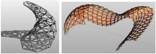
The form creation and conceptual design API can be seen as a subset of the new Revit 2010 family API. It includes new point and curve objects, form making tools, and new surfaces that can be divided, patterned and panelised. You can use it to create schematic studies for curtain system designs and structural framing layouts, and even apply real curtain panels to your form with these new and easy-to-use tools.
- New point and curve objects
- New form-making tools
- Resulting surfaces can be divided, patterned, and panelised

Form Creation Topics
The form creation API provides the following main areas of functionality: points, curves created using these points, forms defined by the curves, divided surfaces placed on faces of a form, and curve panel components placed on that surface:
- Points
- Curve by points
- Forms: extrusion, loft, revolve, swept blend
- Divided surface and panel components
Reference Point and Curve by Points
- Reference points can be created using XYZ, Transform, on edge, at edge/edge or edge/face intersection, on a face or on a plane
- ReferencePointArray, an array of reference points for curve creation
- NewCurveByPoints( ReferencePointArray )
One can start with the reference point class. An instance can be created using a simple XYZ location. This point can be modified using a transformation. The five subclasses of the PointElementReference class allow a point to be defined in relation to some part of the model geometry, such as at the centre of an edge. In that case, the point will update its location if the edge is modified.
The reference point array is an array to store reference points, which is then used to create a curve.
The curve by points method creates a curve using a reference points array.
Forms
Various forms can be created using the following methods provided by the conceptual design API:
- Extrusion: NewExtrusionForm( bool isSolid, ReferenceArray profile, XYZ direction )
- Revolve : NewRevolveForm( bool isSolid, ReferenceArray profile, Reference axis, double startAngle, double endAngle )
- Swept Blend: NewSweptBlendForm( bool isSolid, ReferenceArray path, ReferenceArray profiles )
- Loft: NewLoftForm( bool isSolid, ReferenceArray profiles )
- Cap Surface: NewFormByCap( bool isSolid, ReferenceArray profile )
- Thicken Single Surface: NewFormByThickenSingleSurface( bool isSolid, Form singleSurfaceForm, XYZ thickenDir )
One of the simplest methods is the extrusion method. It creates an extrusion based on a single planar curve loop profile and the extrusion height, which should be perpendicular to the profile plane.

The NewRevolveForm method creates a form by revolving a single planar curve loop profile around an axis. The axis should be in the same plane as the profile.

A swept blend form can be created using a set of two reference arrays: one to determine the path and another to determine the profiles. The start and the end profile should be perpendicular to the path and all the profiles and the paths should be planar and each comprised of one single loop.

Loft is a new surface that can be created using a set of curves, all of which must be planar and each comprised of one single curve. The loft is created by specifying whether it is a solid or void and by the profiles used to create the form.

A cap surface is a flat two-dimensional surface bounded by a single planar loop profile.

The ThickenSingleSurface method can be used to provide a depth to a cap surface, similar to an extrusion. This creates a three dimensional form using a single two dimensional surface.

Modifying Forms
Once a form is created, you can modify its specific sub-elements, using four methods for delete, move, rotate and scale.
Each of the form elements discussed above is defined using profiles. The form element exposes a profile count property called ProfileCount and a method to access each reference on the profile, CurveLoopReferencesOnProfile. You can modify the form at the desired profile by passing in the profile reference to one of the four form modification methods provided on the form element.
while( i < formLoft.ProfileCount )
{
  int move = 3;

  ReferenceArray ref_Array
    = formLoft.get_CurveLoopReferencesOnProfile(
      i, iCurveLoopIndex );

  Reference loft_ref = ref_Array.get_Item( 0 );

  while( move < 14 )
  {
    XYZ XYZmove = new XYZ( move, 0, 0 );
    formLoft.MoveSubElement( loft_ref, XYZmove );
    doc.Save();

    XYZmove = new XYZ( 0, move, 0 );
    formLoft.MoveSubElement( loft_ref, XYZmove );
    doc.Save();

    XYZmove = new XYZ( 0, 0, move );
    formLoft.MoveSubElement( loft_ref, XYZmove );
    doc.Save();

    move = move + 2;
  }
  move = 0;
  i = i + 1;
}
Divided Surface
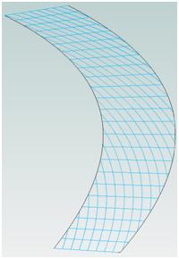
The divided surface functionality places a grid of parallelograms on the surface of a form. You can use the method FamilyItemFactory.NewDividedSurface() to create a divided surface. The appearance of the grid is controlled by the grid rotation angle and spacing rules and U and V direction. The figure shows an example of divided surface application and it values in the property dialog.
The divided surface information can be obtained from a given divided surface object, using the GetDividedSurfaceData method. This method returns the DividedSurfaceData class, which is a container of the divided surface data. From the DividedSurfaceData, you can use GetReferencesWithDividedSurfaces() method to access to references to the divided surface. The following code snippet illustrates the access to DividedSurfaceData from the given form reference with divided surfaces.
form = e as Autodesk.Revit.Elements.Form;

DividedSurfaceData dsData
  = form.GetDividedSurfaceData();

if( dsData != null )
{
  foreach( Reference r in
    dsData.GetReferencesWithDividedSurfaces() )
  {
    dsRefs.Append( r );
  }
}
Here is a grid of parallelograms defined by AllGridRotation, USpacingRule, and VSpacingRule:

Tile Pattern
Once we have a divided surface, the next thing to be done is to apply set of patterns to it. A set of pre-defined patterns is built into the Revit product. The figure below shows an image of these patterns as displayed in the user interface. This set of pre-defined built-in tiling patterns is hard-coded and cannot be modified, nor can new ones be created in 2010.


Tile patterns can be placed on divided surfaces and used as a framework for placing panels.
The following code snippet shows an iteration through the built-in tile pattern enumeration, available from the Document.Settings property. With each of the TilePatternBuiltIn enumeration items, we can get and set a specific pattern to the object type of the divided surface. The call to save the document updates the graphics display, so that the modification becomes visible:
TilePatterns tilepatterns
  = doc.Settings.TilePatterns;

foreach( TilePatternsBuiltIn x in
  Enum.GetValues(
    typeof( TilePatternsBuiltIn ) ) )
{
  divSurface.ObjectType
    = tilepatterns.GetTilePattern( x );
  doc.Save();
}
Curtain Panel
A curtain panel is a special mass family hosted by a grid, similar to window and door families hosted in a curtain wall. When curtain panels are applied to a divided surface, Revit creates family instances of the panel on the surface grid nodes. In the API, the divided surface has an ObjectType property that can be set to the panel to be used on the surface. Setting the ObjectType defines which panel family instances to create for the grid. Each node in the grid has a marker indicating if it is a seed node or not. There is a seed node associated with every panel, but depending on the tile pattern and layout, there will be nodes that are not seed nodes.
- Special mass families built on a sample grid, similar to the host wall in a window or door family
- Applied to a divided surface, Revit creates family instances of the panel on the surface grid nodes
Here are some new family properties that were added to support this functionality:
- Family.IsCurtainPanelFamily
- Family.CurtainPanelHorizontalSpacing
- Family.CurtainPanelVerticalSpacing
- Family.CurtainPanelTilePattern
Once the curtain panel is in place, you can iterate through the grid and access each panel to perform a certain action. The code snippet below demonstrates how to iterate through the grid, access each node, and change the type of panel.
To iterate through the nodes, you can use the GridNode class that encapsulates UV indices to node calculation. You can obtain the number of divisions in UV directions through the DividedSurface properties NumberOfUGridlines and NumberOfVGridlines, respectively. You can access each tile or panel using the GetTileFamilyInstance method on the divided surface. This method accepts an instance of a grid node object holding the U and V index values and a rotation parameter. From this, the desired action can be applied to each of the panel. For example, in the sample below, the symbol of the family instance is changed to a glazed type.
GridNode gn = new GridNode();

int u = 0;
while( u < ds.NumberOfUGridlines )
{
  gn.UIndex = u;

  int v = 0;
  while( v < ds.NumberOfVGridlines )
  {
    gn.VIndex = v;

    if( ds.IsSeedNode( gn ) )
    {
      FamilyInstance fi
        = ds.GetTileFamilyInstance( gn, 0 );

      if( fi != null )
      {
        // implement logic here with each tile,
        // for example change the type to glazing

        fi.Symbol = pFamilySymbol.glazed;
      }
    }
    v = v + 1;
  }
  u = u + 1;
}
Form Creation SDK Samples
The Revit SDK provides the following samples illustrating various aspects of the form creation API:
- DistanceToPanels: Measure the distance from a selected object to all divided surface panels
- MeasurePanelArea: Divided surface panel measurement and modification
- NewForm: Create ExtrusionForm, CapForm, RevolveForm, SweptBlendForm and Loft Form
- PanelEdgeLengthAngle: Divided surface panel measurement
Form Creation Labs
We implemented three new commands demonstrating the form creation API in a new Labs7 module of the Revit API introduction labs:
- Lab7_1_CreateForm: Create a loft form using reference points and curve by points.
- Lab7_2_CreateDividedSurface: Create a divided surface using reference of a face of the form.
- Lab7_3_ChangeTilePattern: Change the tiling pattern of the divided surface using the built-in TilePattern enumeration.
Thank you very much Saikat for this great overview!