DWG and DWF Family Creation
Here is another question on family creation, this time not regarding parameters, but the geometrical content and reuse of existing geometry.
Revit is a strongly parametric system, and the Revit family management obviously also. However, if one happens to have important predefined static geometry for certain components, that can be reused as well. It is of course a shame to be using static, non-parametric geometry in an environment with such powerful support for parameterisation. In some cases, however, reusing pre-existing content is the most efficient solution. The following question deals with this kind of geometry reuse.
Question: How can I use existing DWG and DWF files to define new Revit types and create families? In particular:
- Do I need to create a separate family or a family type for each DWG or DWF file?
- Do I need to create a physical RFA file before inserting it into the project, or can I use the API to insert the in-memory Document object directly? The RFA file is not required later, and the inserted family is embedded in the project.
Answer: The first place to look for an idea of how to automate importing external CAD files into a family is the Revit SDK sample DWGFamilyCreation. It shows how to import a DWG file into a family document, create a new type, and add parameters to it. In this sample, one single DWG file is imported into the family document. The new type is defined, and two parameters are added to it for the DWG file name and creation time.
Let's reiterate some basics. In Revit, a family is a collection of the types or symbols it defines. Normally, the types contained in one single family are closely related.
The family file defines the geometry, which can be parameterised. There can be any number of types in a family file. Each type can have parameters, and these parameters can be used to modify the geometry by driving pre-defined dimensions and constraints. Several types can thus share the same geometry.
If the geometry is defined by an imported DWG or DWF file, it will obviously be static and not have any dimensions or constraints that can be driven by parameters. If you import two DWG or DWF files into the same family document, they would by default both be visible. However, portions of the geometry can also be selectively hidden for different types.
If you have a one-to-one correspondence between the types and the DWG or DWF files defining the geometry, you will want to display only the portion of geometry defined by DWG or DWF file X for the corresponding type X. This can be achieved in two ways: either by creating a separate family for each DWG or DWF file, or by adding several DWG or DWF files and hiding all the geometry from the other ones for type X.
Here is an example of binding geometry with family types using DWF files:
In this example, three separate groups of static geometry are loaded into one single family file from three separate DWF files. Three types are created. Each type refers to one group of static geometry, and the other two are hidden for that type.
The three DWF files represent desks of different sizes: 60x30, 60x40, and 72x36.
- Load them into a new family, and create three family types: 60x30, 60x40, and 72x36.
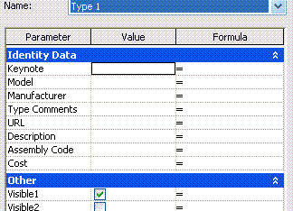
- Add three family type Yes/No parameters: 60x30Visible, 60x40Visible, 72x36Visible.
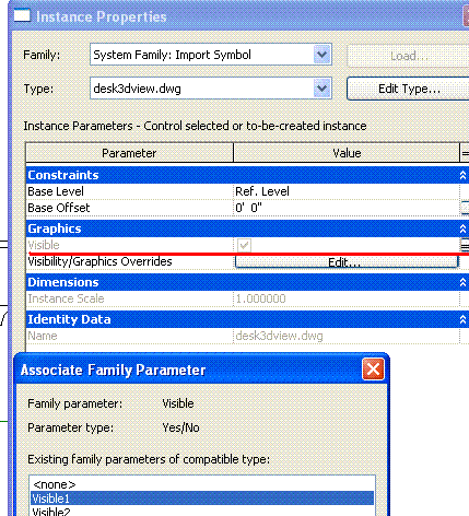
- Bind the visibility parameter to the respective imported instance visibility property:

- Set 60x30Visible to true and the other two parameters to false for type 60x30, and analogously for the other two types:

Now you can control the geometry visibility depending on the selected type.
One can use this approach to load all DWG or DWF files into one single family, create a separate type for each one, and hide all of the other geometry for each, so each type displays exactly one DWG or DWF file.
Alternatively, of course, you can create a separate family file for each DWG or DWF file. The advantage of that would be less complexity and smaller files, and also the possibility to define different parameters for different source files; the disadvantage is the loss of the grouping into a single coherent family, the larger number of files, and ensuing management overhead.
In order to actually load the newly defined family type into a Revit project, one can use one of the two methods for loading families and types provided by the Document class:
- LoadFamily, which loads an entire family and all its types or symbols.
- LoadFamilySymbol, which loads only one specified family type or symbol from a family file.
Both of these are provided in two flavours each, one taking a string argument specifying the file name of the RFA file to load, and the other taking a Document argument. You can use the Document argument overload to load a family document that has not yet been saved in an external file. Therefore, you can create a new family document in memory and load it without saving it first.