Transform Instance Coordinates
We briefly introduced transformations and the Revit Transform class in the overview of the geometry library, and discussed some basic Transform concepts and usage. Now we are well prepared to address a more interesting topic.
Question: I need to be able to find the coordinates of all the vertices of a shape. If I take a simple shape such as a mullion, I am able to select all its faces and vertices, but I am getting confused with the coordinates. The mullion is making use of multiple nested locations: a location point for the wall, a location point for the mullion itself, and finally a location point for each face. These location points are related to each other. Also each face is oriented in a specific way with its own normal vector. My questions are:
- How can I determine the coordinates of a vertex in my world environment? I need to retrieve their X, Y and Z coordinates relative to the origin of my project at 0,0,0.
- How do I know the order of the vertices on the face? Are they always counter-clockwise oriented?
- How can I calculate the result of the nested locations when all of them have their own base point?
Answer: First of all, to explore the geometry defined for Revit elements, it is useful to have a look at the Revit SDK ElementViewer and ObjectViewer samples. They show you how to traverse the element geometry and extract the coordinates you are looking for.
Regarding your question on vertex ordering: if you query a solid for its mesh, the mesh triangle vertices are guaranteed to be counter-clockwise oriented when looking towards the solid from outside.
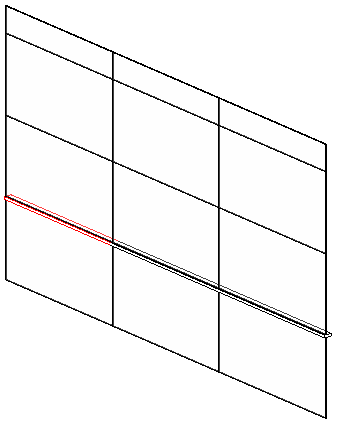
To examine the access to an element's geometry and vertex data, I created a sample model with a mass element, a curtain grid system, and some mullion elements. Here is an image of the curtain grid system and mullion model with one mullion selected:
Looking at this in the ObjectViewer displays the following dialogue with a wireframe image of the mullion:

The geometry of each mullion element contains a symbol, symbol geometry, and a transform. You can observe these elements being iterated by debugging the code and stepping through it in the Visual Studio debugger. I added some own new code to the object viewer to list the coordinates of the geometry traversed. I implemented the following utility functions for formatting real numbers and points, culminating in the definition of ListCurve to print the contents of an array of points:
static public string PluralSuffix( int n )
{
  return 1 == n ? "" : "s";
}

static public string DotOrColon( int n )
{
  return 1 < n ? ":" : ".";
}

static public string RealString( double a )
{
  return a.ToString( "0.##" );
}

static public string PointString( XYZ p )
{
  return string.Format( "({0},{1},{2})",
    RealString( p.X ), RealString( p.Y ),
    RealString( p.Z ) );
}

static public void ListCurve(
  XYZArray pts )
{
  string s = string.Empty;
  foreach( XYZ p in pts )
  {
    if( 0 < s.Length )
    {
      s += ", ";
    }
    s += PointString( p );
  }
  int n = pts.Size;
  System.Diagnostics.Debug.Print(
    "{0} point{1}{2} {3}",
    n, PluralSuffix( n ),
    DotOrColon( n ), s );
}
I then added a new method ListCurves to the class GeometryData to list the contents of its private List<XYZArray> m_curve3Ds member:
private void ListCurves()
{
  int n = m_curve3Ds.Count;

  System.Diagnostics.Debug.Print(
    "\n{0} curve{1}{2}",
    n, Util.PluralSuffix( n ),
    Util.DotOrColon( n ) ) );

  foreach( XYZArray curve in m_curve3Ds )
  {
    Util.ListCurve( curve );
  }
}
You can use the SDK global solution SDKSamples2009.sln to compile and debug this code. It displays the following coordinates on the Visual Studio > Debug > Windows > Output console when I select the mullion:
10 curves:
4 points: (-23.42,6.85,5), (-23.42,7.34,5), (-23.42,7.34,4.84), (-23.42,6.85,5)
4 points: (-23.42,7.34,4.84), (-23.42,6.85,4.84), (-23.42,6.85,5), (-23.42,7.34,4.84)
4 points: (-13.58,6.85,5), (-13.58,7.34,5), (-23.42,6.85,5), (-13.58,6.85,5)
4 points: (-23.42,7.34,5), (-23.42,6.85,5), (-13.58,7.34,5), (-23.42,7.34,5)
4 points: (-13.58,7.34,5), (-13.58,7.34,4.84), (-23.42,7.34,5), (-13.58,7.34,5)
4 points: (-23.42,7.34,4.84), (-23.42,7.34,5), (-13.58,7.34,4.84), (-23.42,7.34,4.84)
4 points: (-13.58,7.34,4.84), (-13.58,6.85,4.84), (-23.42,7.34,4.84), (-13.58,7.34,4.84)
4 points: (-23.42,6.85,4.84), (-23.42,7.34,4.84), (-13.58,6.85,4.84), (-23.42,6.85,4.84)
4 points: (-13.58,6.85,4.84), (-13.58,6.85,5), (-23.42,6.85,4.84), (-13.58,6.85,4.84)
4 points: (-23.42,6.85,5), (-23.42,6.85,4.84), (-13.58,6.85,5), (-23.42,6.85,5)
Please copy and paste this text to an editor of your choice if the lines are too long to display properly in the narrow column in the browser.
To demonstrate concept of applying the nested transformations for the various location points, I implemented a new command CmdTransformedCoords. It is currently tailored to analyse and transform the vertex data of a mullion family instance, but it can obviously easily be adapted to handle other objects as well, or family instances in general.
Here is the code of the Execute method of the new CmdTransformedCoords external command:
Application app = commandData.Application;
Document doc = app.ActiveDocument;
Selection sel = doc.Selection;

Options options = app.Create.NewGeometryOptions();
string s, msg = string.Empty;
int n;
foreach( RvtElement e in sel.Elements )
{
  Mullion mullion = e as Mullion;
  if( null != mullion )
  {
    Location location
      = mullion.Location; // seems to be uninitialised

    LocationPoint lp
      = mullion.AsFamilyInstance.Location
        as LocationPoint;

    GeoElement geoElem
      = mullion.get_Geometry( options );

    GeometryObjectArray objects = geoElem.Objects;
    n = objects.Size;
    s = string.Format(
      "Mullion <{0} {1}> at {2} rotation"
      + " {3} has {4} geo object{5}:",
      mullion.Name, mullion.Id.Value,
      Util.PointString( lp.Point ),
      Util.RealString( lp.Rotation ),
      n, Util.PluralSuffix( n ) );

    if( 0 < msg.Length ) { msg += "\n\n"; }
    msg += s;

    foreach( GeometryObject obj in objects )
    {
      GeoInstance inst = obj as GeoInstance;
      Transform t = inst.Transform;

      s = "  Transform " + Util.TransformString( t );
      msg += "\n" + s;

      GeoElement elem2 = inst.SymbolGeometry;
      foreach( GeometryObject obj2 in elem2.Objects )
      {
        Solid solid = obj2 as Solid;
        if( null != solid )
        {
          FaceArray faces = solid.Faces;
          n = faces.Size;

          s = string.Format(
            "  {0} face{1}, face point > WCS point:",
            n, Util.PluralSuffix( n ) );

          msg += "\n" + s;

          foreach( Face face in solid.Faces )
          {
            s = string.Empty;
            Mesh mesh = face.Triangulate();
            foreach( XYZ p in mesh.Vertices )
            {
              s += ( 0 == s.Length ) ? "    " : ", ";
              s += string.Format( "{0} > {1}",
                Util.PointString( p ),
                Util.PointString( t.OfPoint( p ) ) );
            }
            msg += "\n" + s;
          }
        }
      }
    }
  }
}
if( 0 == msg.Length )
{
  msg = "Please select some mullions.";
}
Util.InfoMsg( msg );
return CmdResult.Failed;
It iterates over all selected elements and analyses mullion elements only. It extracts the mullion Location property, which is apparently not initialised. It uses its AsFamilyInstance property to retrieve a family instance for the mullion. That also has a Location property, and this is correctly initialised to a LocationPoint.Details like this are not documented and need to be explored on a case by case basis in the debugger or using RvtMgdDbg. An interesting thing about the LocationPoint object is that it has a rotation as well as point data. The mullion name, element id, location point and number of its geometry objects are listed.
We iterate over the latter and expect to find a Geometry Instance object. This object is used to represent a transformed copy of some symbol geometry. The symbol geometry is defined once only and can then be reused in various locations. The important properties of the Geometry Instance object are thus its transformation, which we store in the variable t, and the reference to its symbol geometry.
The symbol geometry again contains geometry elements, and one of them is the solid. We extract its faces, query each one for its mesh to obtain a triangulation, and iterate over the mesh vertices.
The thing to pay attention to here is the series of transformations that need to be applied to each geometrical object in the nested hierarchy. In this case, the hierarchy is quite flat, and there is only one transformation involved, which is the location of the mullion in model space. The very innermost loop iterates over the vertices of the mesh of the faces of the solid. There, I print out both the location point defining the position of the mullion as a family instance, as well as the mullion geometry instance transformation data, which amount to the same, followed by the original and transformed face vertices.
The vertex coordinates are listed once in the mullion instance's local coordinate space, and then again in the world coordinate system or WCS. The latter coordinates are obtained by applying the transform t, which is the instance transform, to the vertex p, by the call t.OfPoint( p ). Applying this transformation to the points retrieved from the faces produces the WCS points you are looking for. Here is the result for two of the mullions in the test model I created:
Mullion <50mm x 150mm 127323> at (-13.58,7.1,4.92) rotation 3.14 has 1 geo object:
  Transform ((-13.58,7.1,4.92),(0,0,1),(0,-1,0),(1,0,0))
  5 faces, face point > WCS point:
    (0.08,0.25,-9.84) > (-23.42,6.85,5), (0.08,-0.25,-9.84) > (-23.42,7.34,5), (-0.08,-0.25,-9.84) > (-23.42,7.34,4.84), (-0.08,0.25,-9.84) > (-23.42,6.85,4.84)
    (0.08,0.25,0) > (-13.58,6.85,5), (0.08,-0.25,0) > (-13.58,7.34,5), (0.08,-0.25,-9.84) > (-23.42,7.34,5), (0.08,0.25,-9.84) > (-23.42,6.85,5)
    (0.08,-0.25,0) > (-13.58,7.34,5), (-0.08,-0.25,0) > (-13.58,7.34,4.84), (-0.08,-0.25,-9.84) > (-23.42,7.34,4.84), (0.08,-0.25,-9.84) > (-23.42,7.34,5)
    (-0.08,-0.25,0) > (-13.58,7.34,4.84), (-0.08,0.25,0) > (-13.58,6.85,4.84), (-0.08,0.25,-9.84) > (-23.42,6.85,4.84), (-0.08,-0.25,-9.84) > (-23.42,7.34,4.84)
    (-0.08,0.25,0) > (-13.58,6.85,4.84), (0.08,0.25,0) > (-13.58,6.85,5), (0.08,0.25,-9.84) > (-23.42,6.85,5), (-0.08,0.25,-9.84) > (-23.42,6.85,4.84)

Mullion <50mm x 150mm 127325> at (6.11,7.1,4.92) rotation 3.14 has 1 geo object:
  Transform ((6.11,7.1,4.92),(0,0,1),(0,-1,0),(1,0,0))
  5 faces, face point > WCS point:
    (0.08,-0.25,0) > (6.11,7.34,5), (-0.08,-0.25,0) > (6.11,7.34,4.84), (-0.08,0.25,0) > (6.11,6.85,4.84), (0.08,0.25,0) > (6.11,6.85,5)
    (-0.08,0.25,0) > (6.11,6.85,4.84), (0.08,0.25,0) > (6.11,6.85,5), (0.08,0.25,-9.84) > (-3.74,6.85,5), (-0.08,0.25,-9.84) > (-3.74,6.85,4.84)
    (-0.08,-0.25,0) > (6.11,7.34,4.84), (-0.08,0.25,0) > (6.11,6.85,4.84), (-0.08,0.25,-9.84) > (-3.74,6.85,4.84), (-0.08,-0.25,-9.84) > (-3.74,7.34,4.84)
    (0.08,-0.25,0) > (6.11,7.34,5), (-0.08,-0.25,0) > (6.11,7.34,4.84), (-0.08,-0.25,-9.84) > (-3.74,7.34,4.84), (0.08,-0.25,-9.84) > (-3.74,7.34,5)
    (0.08,0.25,0) > (6.11,6.85,5), (0.08,-0.25,0) > (6.11,7.34,5), (0.08,-0.25,-9.84) > (-3.74,7.34,5), (0.08,0.25,-9.84) > (-3.74,6.85,5)
Again, you may need to copy and paste this text to an editor to see the full line length.
As expected, the symbol geometry is identical for both mullions, and the only difference lies in their transformations, which lead to the differing WCS positions of their vertices.
We had to explore how to extract all this data by implementing the traversals one by one and step by step, examining the results in the debugger, and then implementing the next step to analyse where that would lead us, recompiling and retesting iteratively to dig deeper and deeper into this structure. This is standard procedure, so you may as well get used to it.
Here is version 1.0.0.28 (file no longer available) of the complete Visual Studio solution with the new CmdTransformedCoords command.