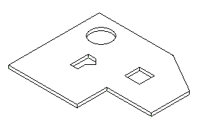
Developers have frequently asked how to determine the boundary polygons of a horizontal slab, e.g. the loops formed by the bottom edges of all the vertical or 'side' faces in this floor:

In this case, there is one outer and three inner loops, one of which is circular.
There are several different possible approaches to obtain this information, and you will need to decide which is simplest or most effective or optimally suited to provide the data you require in each individual case. Here is a suggestion for a very straightforward algorithm: determine the slab solid, iterate over its faces, ignore all non-horizontal faces, and determine which of the horizontal ones has the lowest Z coordinate. Query the lowest face for its edge loops, and collect all its vertices into a structure for handling the polygon data.
I have implemented an external command CmdSlabBoundary realising this algorithm. For the polygon data, I use a list of lists of points. Each list of points represents one closed polygonal loop. This means that non-linear polygon edges will have to be approximated by straight segments. If you need to handle other curve types such as circular arcs or ellipses exactly, you would have to enhance this definition. It currently only handles planar faces on horizontal slabs. It uses the Edge Tesselate method, which returns a polyline approximation to the edge, to extract the points to be added to the boundary polygon.
Here is the code for the mainline of the command. It implements some useful code to determine which floor elements to process. It first checks whether anything at all has been selected. If so, it extracts the floor elements from the selection and returns with an error message if none are found. If nothing has been preselected by the user before starting the command, it selects all floor elements from the model, and again returns with an error message if none are found. Then, for each floor, the geometry is extracted and the solid is passed into the GetBoundary() method for analysis:
public CmdResult Execute(
  ExternalCommandData commandData,
  ref string message,
  ElementSet elements )
{
  Application app = commandData.Application;
  Document doc = app.ActiveDocument;

  List<RvtElement> floors = new List<RvtElement>();
  Selection sel = doc.Selection;
  if( 0 < sel.Elements.Size )
  {
    foreach( RvtElement e in sel.Elements )
    {
      if( e is Floor )
      {
        floors.Add( e );
      }
    }
    if( 0 == floors.Count )
    {
      message = "Please select some floor elements.";
      return CmdResult.Failed;
    }
  }
  else
  {
    doc.get_Elements( typeof( Floor ), floors );
    if( 0 == floors.Count )
    {
      message = "No floor elements found.";
      return CmdResult.Failed;
    }
  }

  List<List<XYZ>> polygons = new List<List<XYZ>>();
  Options opt = app.Create.NewGeometryOptions();

  foreach( Floor floor in floors )
  {
    GeoElement geo = floor.get_Geometry( opt );
    GeometryObjectArray objects = geo.Objects;
    foreach( GeometryObject obj in objects )
    {
      Solid solid = obj as Solid;
      if( solid != null )
      {
        GetBoundary( polygons, solid );
      }
    }
  }

  int n = polygons.Count;

  Debug.WriteLine( string.Format(
    "{0} boundary loop{1} found.",
    n, Util.PluralSuffix( n ) ) );

  Creator creator = new Creator( app );
  creator.DrawPolygons( polygons );

  return CmdResult.Succeeded;
}
Here is the implementation of GetBoundary(); I added a constant value to offset the boundary polygons downward a bit, away from the slab edge, so that they are more clearly visible:
const double _offset = 0.1;

bool GetBoundary(
  List<List<XYZ>> polygons,
  Solid solid )
{
  PlanarFace lowest = null;
  FaceArray faces = solid.Faces;
  foreach( Face f in faces )
  {
    PlanarFace pf = f as PlanarFace;
    if( null != pf && IsHorizontal( pf ) )
    {
      if( ( null == lowest )
        || ( pf.Origin.Z < lowest.Origin.Z ) )
      {
        lowest = pf;
      }
    }
  }
  if( null != lowest )
  {
    XYZ p, q = XYZ.Zero;
    bool first;
    int i, n;
    EdgeArrayArray loops = lowest.EdgeLoops;
    foreach( EdgeArray loop in loops )
    {
      List<XYZ> vertices = new List<XYZ>();
      first = true;
      foreach( Edge e in loop )
      {
        XYZArray points = e.Tessellate();
        p = points.get_Item( 0 );
        if( !first )
        {
          Debug.Assert( p.AlmostEqual( q ),
            "expected subsequent start point"
            + " to equal previous end point" );
        }
        n = points.Size;
        q = points.get_Item( n - 1 );
        for( i = 0; i < n - 1; ++i )
        {
          XYZ v = points.get_Item( i );
          v.Z -= _offset;
          vertices.Add( v );
        }
      }
      q.Z -= _offset;
      Debug.Assert( q.AlmostEqual( vertices[0] ),
        "expected last end point to equal"
        + " first start point" );
      polygons.Add( vertices );
    }
  }
  return null != lowest;
}
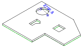
Here is the result displaying the model lines added after processing, with all lines offset downwards from the slab edge by 0.1 feet, and one of the edges approximating the bottom of the circular opening highlighted:

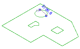
Finally, here are the model lines isolated to distinguish them better from the slab:

I hope this provides a good geometrical analysis example and a starting point for further exploration. Obviously, I am interested in any improvements you may have or bugs that you find.
I am adding a new version 1.0.0.9 of the complete Visual Studio solution here, including the new CmdSlabBoundary class as well as all other commands discussed so far.